Drilling apparatus with percussive action cutter

a technology of percussive action and drilling equipment, which is applied in drilling drives, drilling drives, and surveying, etc., can solve the problems of limiting the cutting effectiveness of the bit, and achieve the effect of facilitating a greater degree of control

Inactive Publication Date: 2007-08-09
ANDERGAUGE
View PDF10 Cites 14 Cited by
  • Summary
  • Abstract
  • Description
  • Claims
  • Application Information

AI Technical Summary

Benefits of technology

[0008] It is among the objectives of embodiments of the present invention to provide an improved drilling apparatus which provides or at least facilitates a greater degree of control in a drilling apparatus having a percussive action cutter provided in combination with another form of cutter.
[0010] The combination of a percussive action cutter with a cutter of another form, such as a roller cone or a fixed cutter, such as a PDC cutter, offers many advantages over conventional drilling apparatus and drill bits. For example, the hammer action of percussive bits is most effective working with relatively light weight applied to the bit, however this may limit the cutting effectiveness of the bit, such that in conventional hammer bits a balance must be struck between these two requirements. However, in the present invention the other cutter may bear a significant proportion of the weight applied to the bit, allowing the percussive action cutter to operate more effectively. Indeed, in preferred embodiments of the present invention, substantially all of the mechanical force normally applied to the apparatus, whether by force applied to a drill string from surface or due to the mass of drill collars, the drill string and the like, is applied to or borne by the other cutter. The “weight” applied to the percussive action cutter is a function of applied hydraulic pressure, equivalent to the “pump-open force”, and thus may be controlled independently of the weight applied to the other cutter, and solely with a view to maximising the effectiveness of the percussive action cutter. This division of force between the cutters also serves to utilise the different forces available, that is mechanical force and hydraulic force, in an efficient and effective manner.
[0015] The percussive action cutter may be located to cut a central portion of the bore. Due to the relatively low speed of a rotating drill bit at the bit centre, there are often difficulties experienced in cutting the centre of the bore. Thus, by locating the percussive action cutter centrally, the enhanced cutting action provided by the hammer drill effect will avoid this difficulty. Furthermore, it is generally desirable to rotate percussive action cutters at relatively low speed (10 to 40 rpm), the primary reason for rotation being to expose fresh formation to the individual cutter elements, with higher speeds leading to excessive or accelerated wear of the cutting elements. Merely by locating the percussive action centrally, the linear speed experienced by the cutter elements is of course relatively low in comparison to the other cutters located radially outwardly of the percussive action cutters, which other cutters typically benefit from higher cutting speeds (150 to 200 rpm). Alternatively, or in addition, the percussive action cutter may be biassed rearwardly, conveniently by means of a spring, or otherwise configured, such that the percussive action cutter is normally held slightly off bottom and thus remains in contact with the formation only for the duration of the hammer impact or impulse. The percussive action cutter will thus only make contact with the formation periodically, and for only a fraction of the time the other cutter remains in contact with the formation. This will reduce the rubbing action and wear experienced by the percussive action cutter, even at higher rotary speeds, allowing the apparatus to be rotated at speeds suited to the other cutter without damaging the percussive action cutter.
[0016] A centrally located percussive action cutter may also have a cutting face located forwards of the cutting face of the other cutter, such that the percussive action cutter effectively cuts a pilot hole in the centre of the bore. Of course this facilitates the dislodgement of rock by the following cutter. Furthermore, by providing lateral fluid outlets on the percussive action pilot cutter, ahead of the other cutter, drilling fluid may be injected into the rock formation ahead of the other cutter, facilitating the release of cuttings by the following cutter.
[0018] Means may be provided for indicating that the other cutter is cutting at a faster rate than the percussive action cutter, allowing, for example, the weight applied to the other cutter to be reduced, thus reducing the cutting speed of the other cutter, improving the cutting efficiency of the percussive action cutter, and preventing premature damage and wear to the percussive action cutter, which may have been experiencing excessive applied weight. Such means may take the form of fluid outlets which are closed if the percussive action cutter experiences elevated weight and is forced rearwardly into the body of the apparatus. The resulting change in back pressure will be detectable at surface, allowing remedial action to be taken.
[0020] A centrally located percussive action cutter may be retractable or removable, to allow the cutting of cores by the remaining cutter, to allow passage of other tools or devices through the apparatus, or to facilitate flow of, for example, cement slurry, through the apparatus. Thus, the drilling apparatus may be utilised as a casing shoe. In such applications it is likely that the shoe will be provided with fixed reaming cutters, typically PDC cutters, which tend to require a high applied torque to rotate the cutters to ream out obstructions to the passage of the shoe and following casing; however, casing, and casing threads, tend not to be capable of accommodating elevated torques. By providing a percussive action cutter in the shoe, centrally or otherwise located, the torque required to rotate the shoe may be reduced.

Problems solved by technology

For example, the hammer action of percussive bits is most effective working with relatively light weight applied to the bit, however this may limit the cutting effectiveness of the bit, such that in conventional hammer bits a balance must be struck between these two requirements.

Method used


Image

  • Drilling apparatus with percussive action cutter
  • Drilling apparatus with percussive action cutter
  • Drilling apparatus with percussive action cutter

Examples


first embodiment

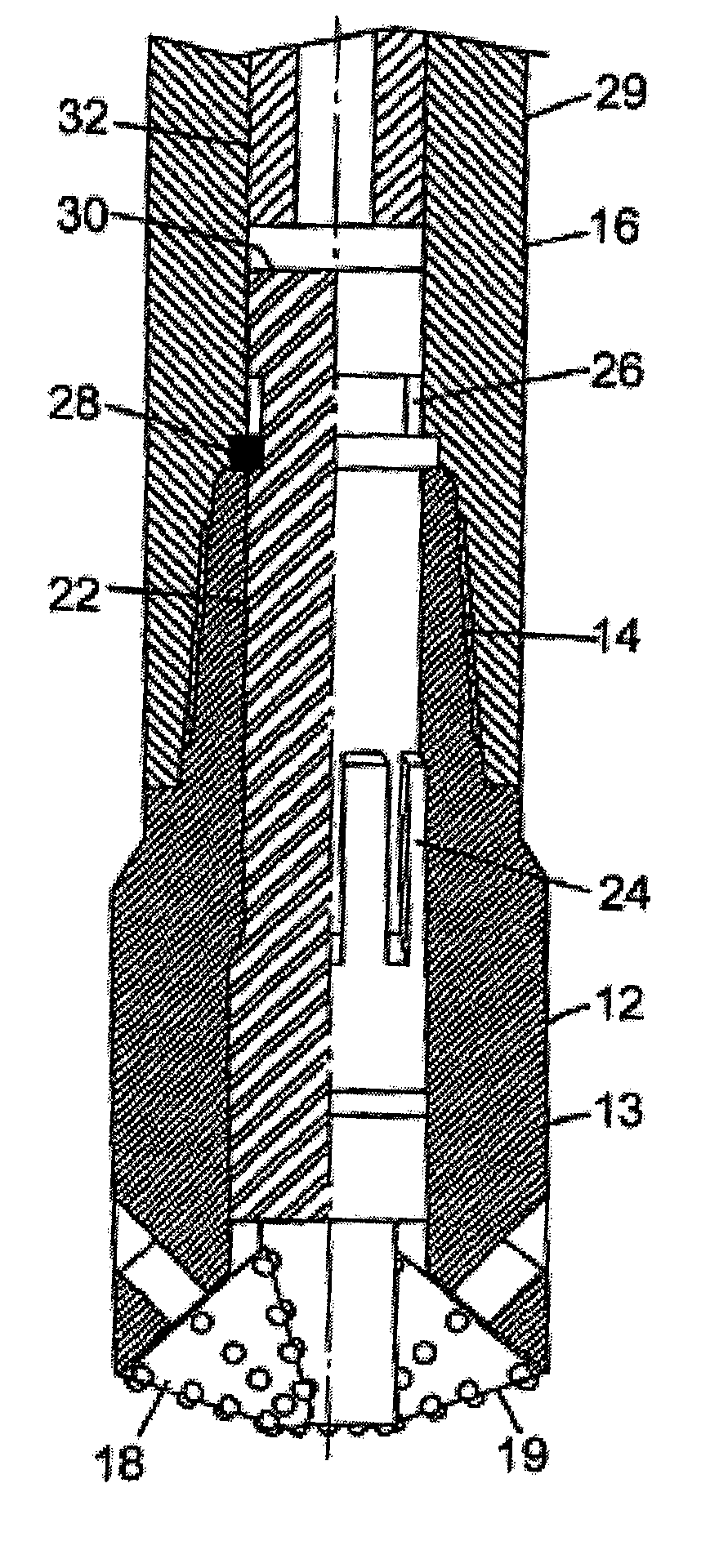
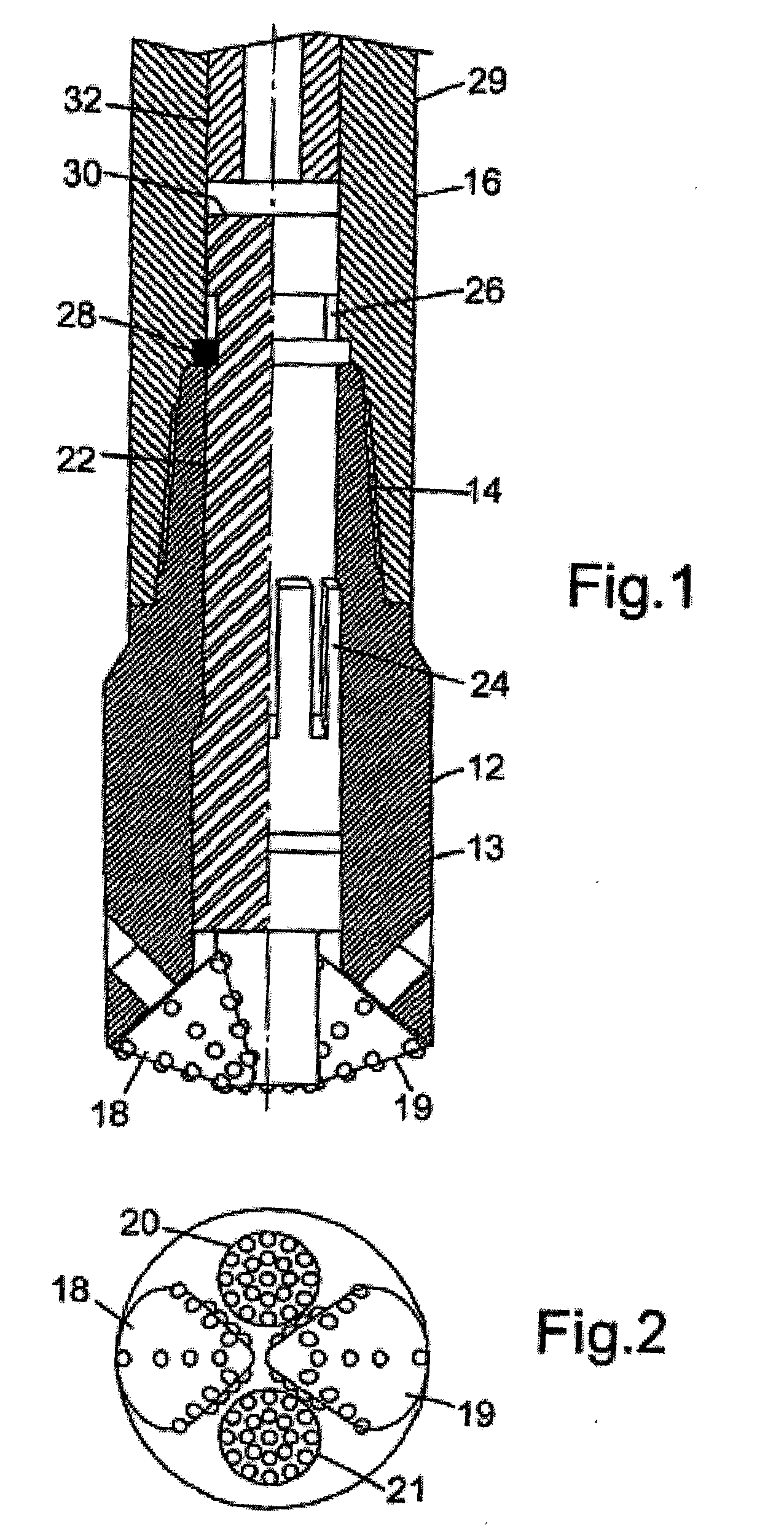
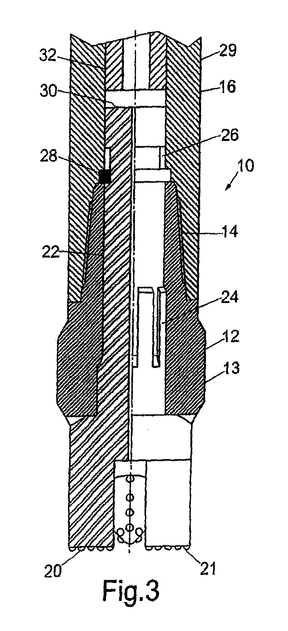
[0031] Reference is first made to FIGS. 1, 2 and 3 of the drawings, which show a drilling apparatus 10 in accordance with the present invention. The apparatus 10 comprises a bit 12 mounted via a pin and box connection 14 to the lower end of a hammer tool 16.

[0032] Mounted on the lower end of the drill bit are two roller cones 18, 19; when the bit 12 is rotated, the cones 18, 19 will roll over the rock formation below the bit 12, crushing or otherwise dislodging cuttings from the rock. The cutting structure of the bit 12 is further defined by two circular cutting faces defined by the ends of a pair of percussive action cutters 20, 21. As may be seen from FIG. 2, the roller cones 18, 19 are positioned on opposite sides of the bit 12, and the percussive action cutters 20, 21 are located in the quadrants between the roller cones 18, 19.

[0033] Both percussive action cutters 20, 21 are mounted on the end of a mandrel 22 which extends through the bit body and into the hammer tool 16. The ...

second embodiment

[0037] Reference is now made to FIGS. 4 and 5 of the drawings, which illustrates drilling apparatus 40 in accordance with the invention. The apparatus 40 shares a number of features with the apparatus 10 described above, however in this apparatus 40 only a single percussive action cutter 42 is provided, and the cutter 42 is located centrally of the drill bit 43. Thus, in the course of a drilling operation, the percussive action cutter 42 will cut a pilot bore, and the following roller cone cutters 44, 45 will effectively provide a reaming operation to bring the bore out to gauge.

[0038] The cutter 42 is mounted on the lower end of a mandrel 46, the upper end of which defines an anvil 48 which is struck by the hammer 50 of the percussive tool 52 provided above the apparatus 40. The tool body 54 defines a bore 56 and the anvil 48 features a seal 58 which provides a sliding seal between the bore 56 and the anvil 48; as with the previous embodiment, the “weight” or force normally applied...

third embodiment

[0044] Reference is now made to FIG. 6 of the drawings, which illustrates, in section, a view of a part of a drilling apparatus 70 in accordance with the present invention. The apparatus 70 shares many features with the apparatus 40 described above, and additionally includes a spring 72 provided between a shoulder on the anvil 74 and the ring 76 trapped between the lower end of the hammer tool body 78 and the upper end of the bit body 80. The spring 72 is selected such that the percussive action cutter 82 is normally held slightly off bottom 84, as illustrated. The cutter 82 thus only contacts the bore bottom 84 when the hammer 86 strikes the anvil 74 and drives the bit ahead such that the cutter 82 impacts the formation. The cutter 82 is thus touching the bottom of the hole only for the duration of the hammer blow, and when the hammer 86 moves away from the anvil 74 the cutter 82 springs back off the bottom of the hole.

[0045] This feature of the apparatus 70 reduces the rubbing act...


PUM


Abstract

A drilling apparatus includes a cutting structure defined by a percussive action cutter and at least one other cutter. The percussive action cutter is adapted to be urged in a drilling direction by hydraulic pressure force, while the other cutter is urged in a drilling direction by mechanical force.

Description

CROSS-REFERENCE TO RELATED APPLICATIONS [0001] This application is a continuation of U.S. application Ser. No. 10 / 488,216, which was filed Aug. 31, 2004, and which is incorporated herein by reference. This application and the Ser. No. 10 / 488,216 application claim the benefit of priority of each of International Application No. PCT / GB02 / 02575, filed Jun. 5, 2002 and published as WO 02 / 099242 A1 on Dec. 12, 2002, United Kingdom (GB) Application No. 0113585.4, filed Jun. 5, 2001, and United Kingdom (GB) Application No. 0114874.1, filed Jun. 19, 2001.FIELD OF THE INVENTION [0002] Embodiments of the invention relate to drilling apparatuses, and in particular to drilling apparatuses for use in drilling bores in earth formations. BACKGROUND OF THE INVENTION [0003] Conventional drill bits, as used for example in the drilling of bores in the oil and gas exploration and production industry, feature a number of toothed roller cones. In use, weight is applied to the rotating bit, and the cones ...

Claims


Application Information

Patent Timeline
Patent Type & Authority Applications(United States)
IPC IPC(8): E21B7/00E21B47/00E21B4/14E21B6/04E21B10/26E21B10/40
CPCE21B4/14E21B10/40E21B10/26E21B6/04
Inventor EDDISON, ALAN MARTYN
Owner ANDERGAUGE
Why Eureka
Try Eureka