Exhaust System and Saddle-Ride Type Vehicle

a technology of exhaust system and saddle rod, which is applied in the direction of machines/engines, cycles, transportation and packaging, etc., can solve the problems of difficult to ensure sufficient chamber volume, interference between the exhaust pipes connected to the rear wall portion and parts, and difficulty in arranging rearwardly thereof, so as to reduce the center of gravity, avoid interference, and the effect of sufficient volum

Inactive Publication Date: 2007-08-09
YAMAHA MOTOR CO LTD
View PDF9 Cites 22 Cited by
  • Summary
  • Abstract
  • Description
  • Claims
  • Application Information

AI Technical Summary

Benefits of technology

[0011] The present invention has been thought of in view of these problems and provides an exhaust system that provides sufficient volume in the chamber while avoiding interference between the chamber and other parts, lowers the center of gravity and concentrates the mass for the vehicle, and reduces differences in exhaust pipe length.

Problems solved by technology

However, since the exhaust pipes are connected to the front and rear wall portions of the chamber, interference between the exhaust pipes connected to the rear wall portion and parts (for example, a suspension device and its bracket shown in FIG. 1 of JP-UM-A-62-34114) arranged rearwardly thereof is an issue.
Moreover, it is difficult to ensure enough chamber volume since the chamber has a cross section in the form of an inverse triangle and is small-sized in a longitudinal direction of a vehicle.
This causes a problem since the engine is a heavy part and the center of gravity of the vehicle cannot be lowered.
If the chamber is in a location other than below the engine, the relatively heavy muffler is also separated from the engine, thus causing a problem in that mass concentration is hindered.
Further, when the chamber is in a location other than below the engine, the distance of the front and rear cylinder banks from the front and rear wall portions of the chamber changes, causing a problem in that different exhaust pipe lengths are required.

Method used


Image

  • Exhaust System and Saddle-Ride Type Vehicle
  • Exhaust System and Saddle-Ride Type Vehicle
  • Exhaust System and Saddle-Ride Type Vehicle

Examples


Embodiment Construction

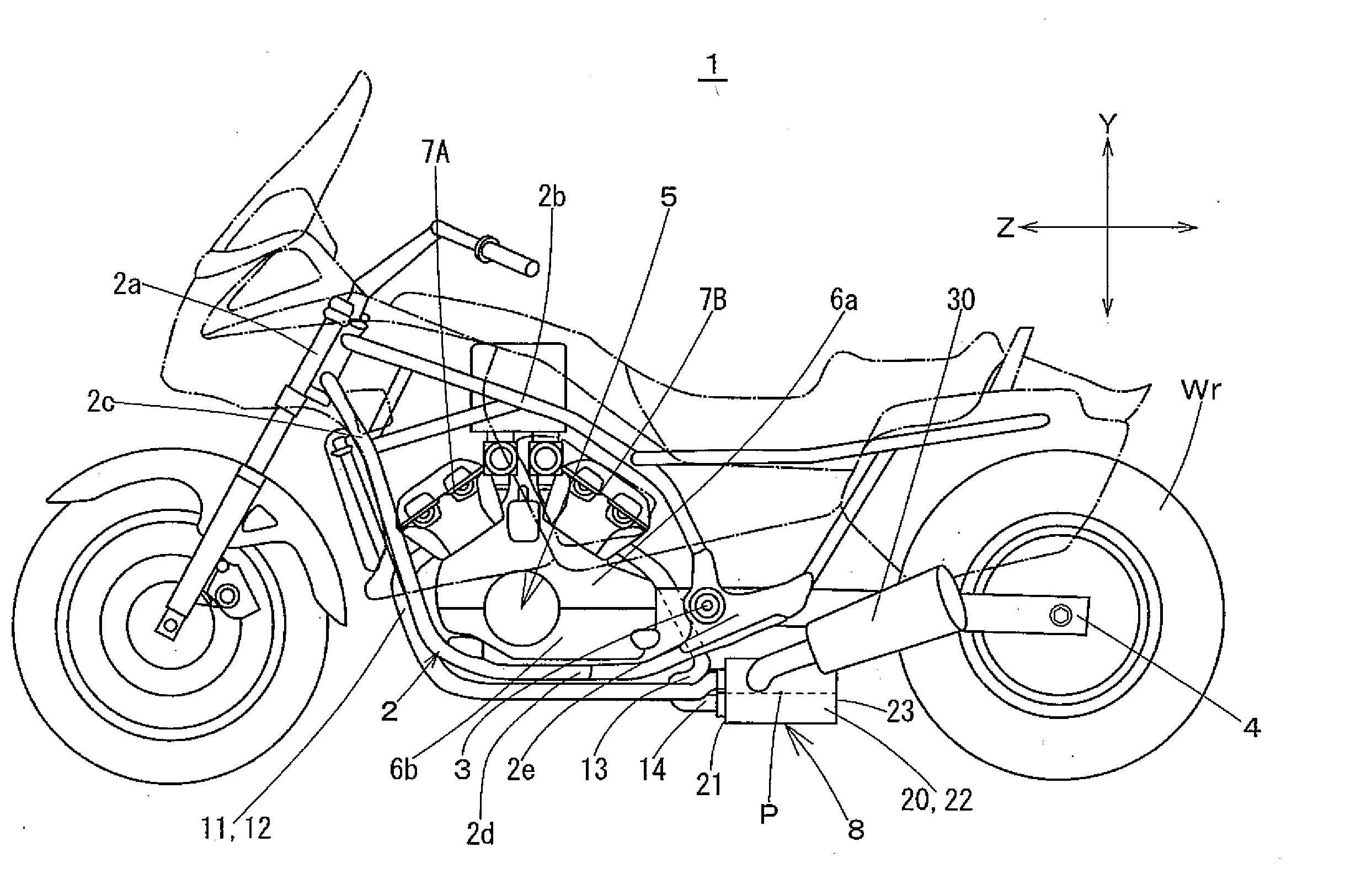
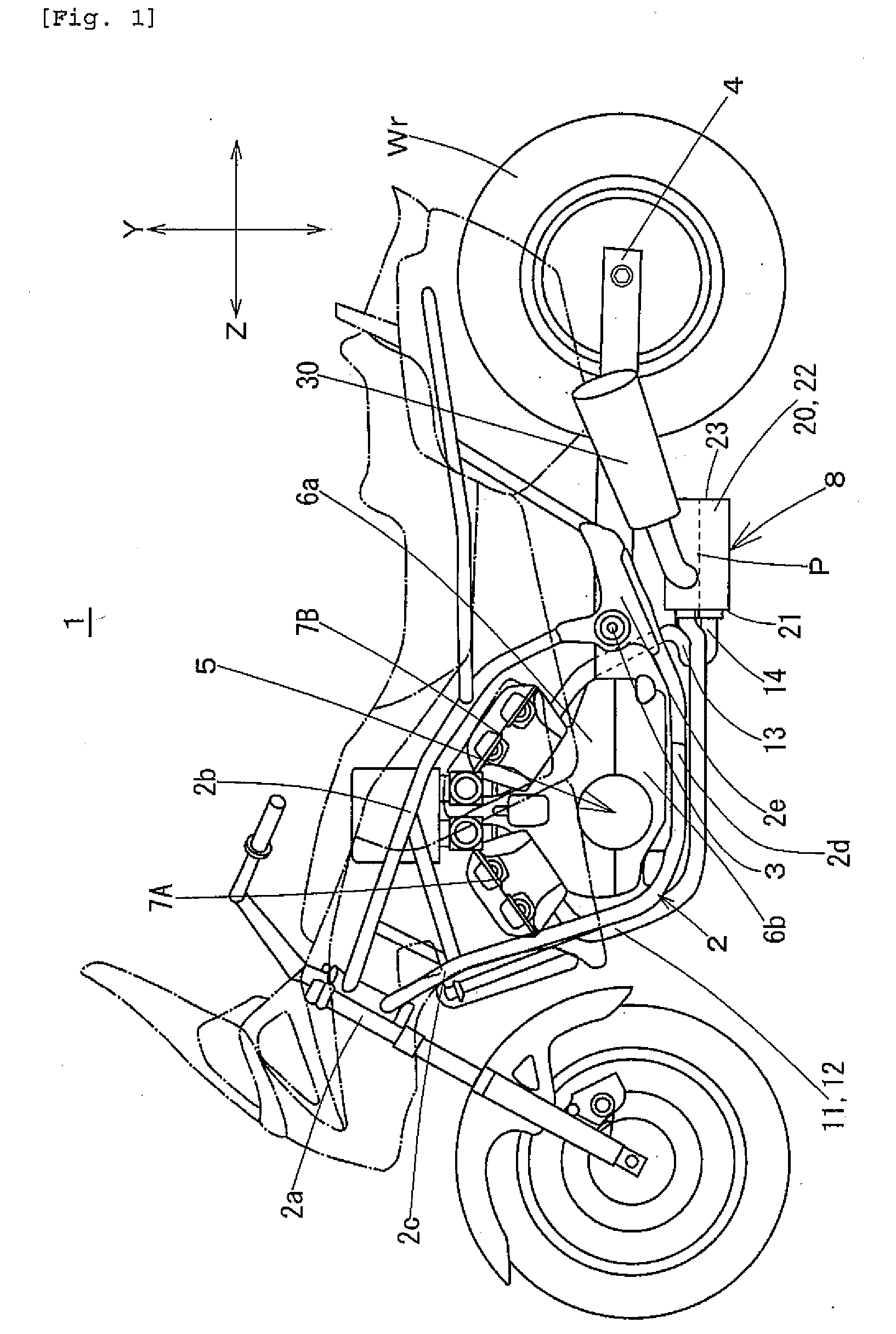
[0039] An exhaust system and a saddle-ride type vehicle according to an embodiment of the invention are described below with reference to the drawings. First, with reference to FIG. 1, a saddle-ride type vehicle is described on which an exhaust system according to the invention is mounted.

[0040] Reference numeral 1 denotes a motorcycle (saddle-ride type vehicle). A frame 2 of motorcycle 1 comprises a steering head pipe 2a at a front end thereof. A rearwardly and obliquely downwardly extending main tube 2b and a downwardly extending downtube 2c are connected to steering head pipe 2a. A lower end of downtube 2c extends substantially horizontally toward the rear, and a rear end of extension 2d is connected to a rear end of main tube 2b through a rear arm bracket 2e.

[0041] A rear arm (support member) 4 is mounted to rear arm bracket 2e through a pivot shaft 3 to be able to swing. Rear arm 4 swings vertically about pivot shaft 3 as a center of rotation to support a rear wheel Wr.

[0042...


PUM


Abstract

An exhaust system for a saddle-ride type vehicle provides sufficient volume in a chamber while avoiding interference between the chamber and other parts. The vehicle center of gravity is lowered and differences in exhaust pipe length are reduced. Exhaust pipes are connected to combustion chambers of front and rear cylinder banks of a V-type engine. A chamber is connected to the exhaust pipes and mufflers are connected to the chamber. The chamber has an exhaust pipe connection wall to which the exhaust pipes are connected and opposing muffler connection walls. The mufflers are connected to positions on the muffler connection walls closer to the engine relative to a center in a longitudinal direction of the vehicle.

Description

RELATED APPLICATIONS [0001] This application claims the benefit of priority under 35 USC 119 of Japanese patent application no. 2005-224719, filed on Aug. 2, 2005, which application is hereby incorporated by reference in its entirety. BACKGROUND OF THE INVENTION [0002] 1. Field of the Invention [0003] The present invention relates to an exhaust system for a saddle-ride type vehicle. [0004] 2. Description of Related Art [0005] Conventionally, some saddle-ride type vehicles such as a motorcycle, a four-wheel buggy, a snowmobile, or the like have a V-type engine, in which two cylinder banks are arranged in a substantially V-type configuration. In such vehicles, an exhaust system having exhaust pipes between combustion chambers of the cylinder banks and a chamber [0006] For example, JP-UM-A-62-34114 discloses an exhaust system for a V-type engine of a motorcycle in which a chamber having a cross section in the form of a substantially inverse triangle is arranged below a V-type engine. E...

Claims


Application Information

Patent Timeline
Patent Type & Authority Applications(United States)
IPC IPC(8): B60K13/04B62M7/02F01N13/08F01N13/10
CPCF01N1/02F01N13/1805F01N13/10
Inventor NAKAYAMA, YOSHIHARU
Owner YAMAHA MOTOR CO LTD
Why Eureka
Try Eureka