Connection between two parts, and associated connection method

a technology of connecting parts and connecting methods, applied in the field of connecting parts, can solve the problems of affecting durability, connection is subjected to only a comparatively light load, and often does not achieve the desired stability, etc., and achieves greater adhesive effects, increased load bearing capacity, and increased stability

Inactive Publication Date: 2007-08-09
DAIMLER AG
View PDF4 Cites 10 Cited by
  • Summary
  • Abstract
  • Description
  • Claims
  • Application Information

AI Technical Summary

Benefits of technology

[0004] The present invention is concerned with the problem of specifying, for a connection of the type initially mentioned, an improved embodiment which, in particular, possesses increased stability.
[0005] The invention is based on the concept of providing, in addition to the plastic connection, an adhesive connection consisting of a cured adhesive. Adhesive connections can generate considerably greater adhesive effects on the surfaces of the parts than plastic connections and, in the cured state, possess a markedly higher load bearing capacity. Overall, the connection according to the invention possesses a markedly increased durability owing to the combination of the plastic connection with the adhesive connection.
[0006] The connection proposed according to the invention is particularly advantageous with regard to a production process in which a connection of this type is produced. When an adhesive connection is produced, the adhesive must first cure in order to generate the desired strength of the adhesive connection. During the curing process, the two parts to be connected to one another via the adhesive connection have to be fixed in relation to one another. In the connection according to the invention, this fixing can be implemented rather quickly with the aid of the plastic connection which has its strength immediately after the cooling of the injection-molded plastic. It is thereby possible, in particular, after the adhesive has been applied and after the plastic connection has been made, to process the parts further and/or to deliver them to other processing stations while the adhesive is not yet cured. It is assumed, in this case, that, during the time-consuming curing process, the connection is subjected to only a comparatively light load as a result of the further processing of the parts. However, these light loads

Problems solved by technology

In specific applications, particularly in the automobile sector, it was shown that connections of this type often do not achieve the desired stability, since, for example, the operating conditions, such as, for example, oscillations, which occur when a motor vehicle is in operation, are highly detrimenta

Method used


Image

  • Connection between two parts, and associated connection method
  • Connection between two parts, and associated connection method

Examples


Embodiment Construction

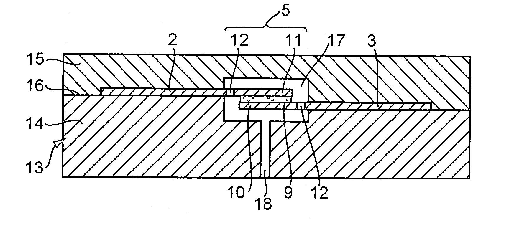
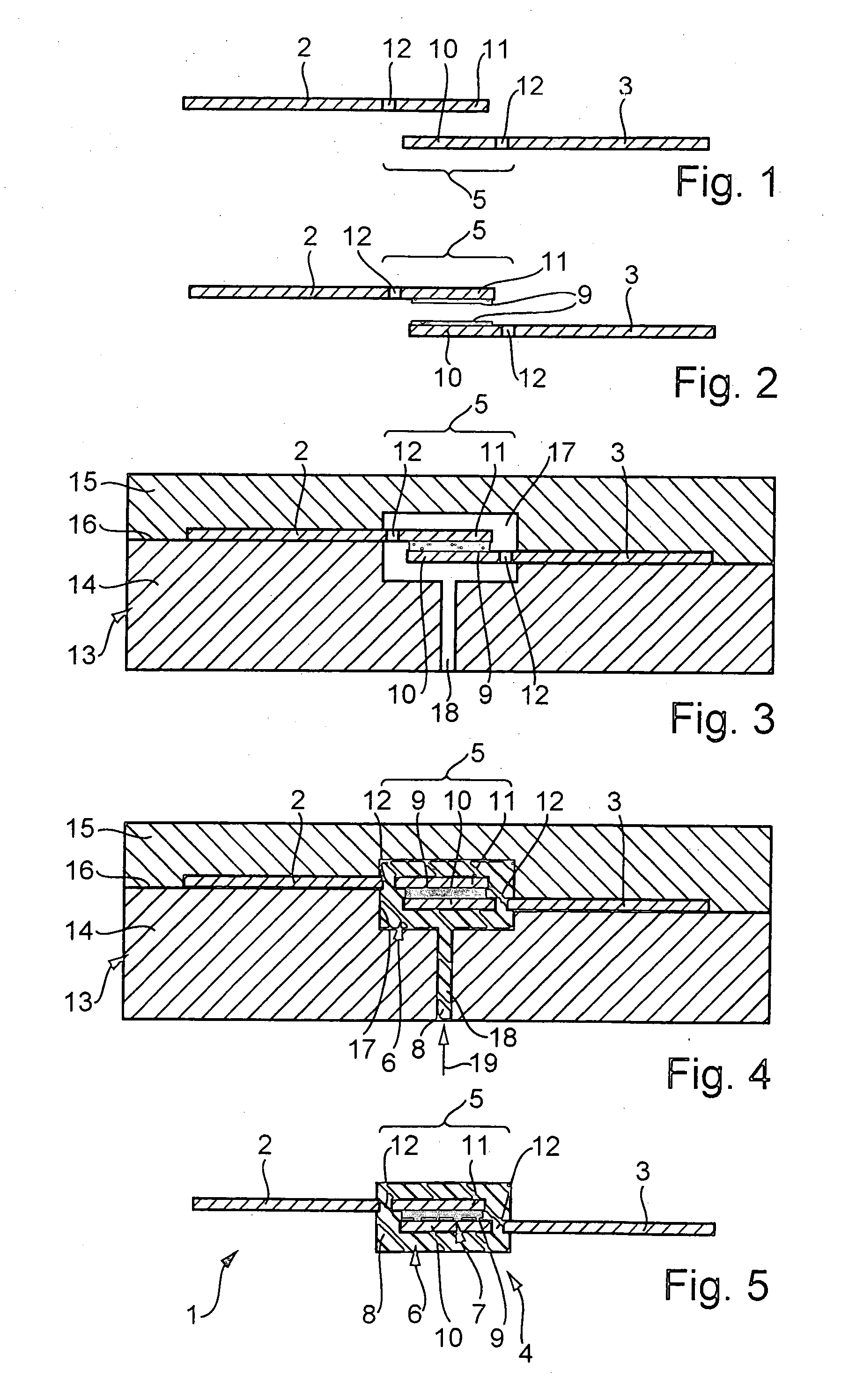
[0018]FIG. 5 shows a composite part 1 which is composed of two individual parts, to be precise, of a first part 2 and of a second part 3, the two parts 2, 3 being connected to one another via the aid of a connection 4 according to the invention. The parts 2, 3 may be, as here, metal sheets which are provided at least on one side with a surface coating.

[0019] The parts 2, 3 are, in particular, coil-coated metal sheets which are delivered on rolls.

[0020] The connection 4 according to the invention includes in a connection zone 5 identified by a curly bracket, a plastic connection 6 and an adhesive connection 7. The plastic connection 6 consists of an injection-molded plastic 8 and connects the two parts 2, 3 to one another in the connection zone 5. In contrast, the adhesive connection 7 consists of a cured adhesive 9 which likewise connects the two parts 2, 3 to one another in the connection zone 5. In the connection zone 5, the two parts 2, 3 overlap one another in each case at an ...


PUM

PropertyMeasurementUnit
Fractionaaaaaaaaaa
Adhesivityaaaaaaaaaa

Abstract

A connection ( 4 ) between two parts ( 2, 3 ), in particular in a motor vehicle. The two parts ( 2, 3 ) are connected to one another in a connection zone ( 5 ) via a plastic connection ( 6 ) consisting of an injection-molded plastic ( 8 ). Additionally, the two parts ( 2, 3 ) are connected to one another in the connection zone ( 5 ) via an adhesive connection ( 7 ) consisting of a cured adhesive ( 9 ).

Description

BACKGROUND AND SUMMARY OF THE INVENTION [0001] The present invention relates to a connection between two parts, in particular in a motor vehicle. [0002] Gillman Patent document DE 100 29 411 A1 discloses a connection between two metal parts, in which a plastic connection which consists of an injection-molded plastic and via which the two parts are connected to one another is formed in a connection zone. In order for the two parts to also be connected positively to one another with the aid of the plastic connection, one part may have a plurality of passage orifices in the connection zone. The orifices are filled with plastic. [0003] In specific applications, particularly in the automobile sector, it was shown that connections of this type often do not achieve the desired stability, since, for example, the operating conditions, such as, for example, oscillations, which occur when a motor vehicle is in operation, are highly detrimental to the durability of the connection. [0004] The pr...

Claims


Application Information

Patent Timeline
IPC IPC(8): B60P3/00B29C45/14B29C65/48B29C65/70B29C65/72B62D27/02B62D29/00
CPCB29C45/14467B29C65/483B29C65/72B29C66/1122B29C66/43B29K2105/0097B29L2031/30B62D27/026B62D29/001B62D29/005B29C65/70B29C65/4835B62D29/004B29C65/00
Inventor EIPPER, KONRADKLEPSCH, BERNDKNOTHE, JUERGENSPIES, BERNHARD
Owner DAIMLER AG
Why Eureka
Try Eureka