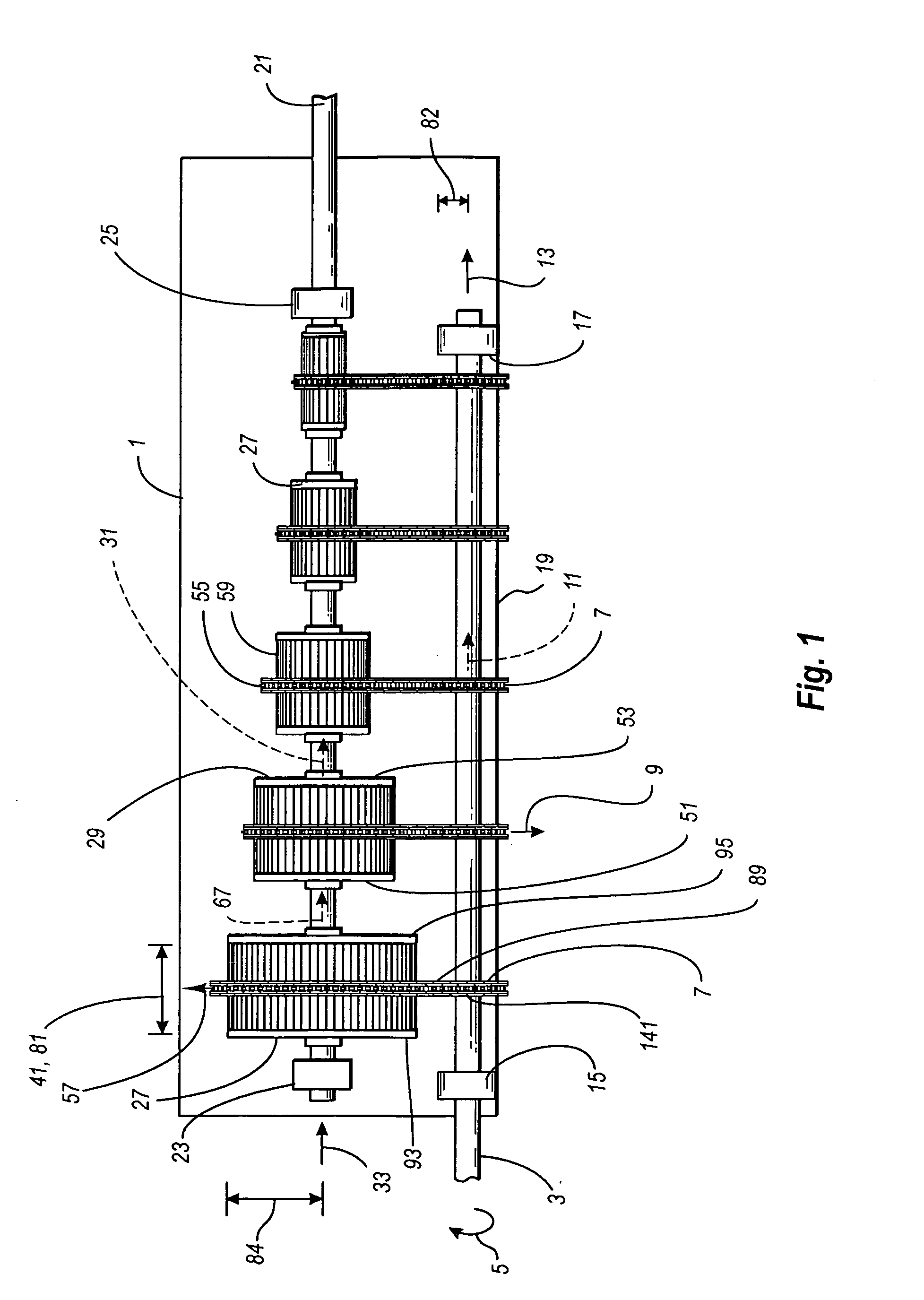
[0004] An input shaft receives
rotational energy from an
energy source such as an automobile engine or an
electric motor. The input shaft for a preferred embodiment has a plurality of input sprockets which extend radially from the input shaft. An inboard input bearing and an outboard input bearing provide stability for the input shaft and provide for it to be anchored to a transmission support or to a transmission housing in the case of an automobile transmission. An output shaft, which is likewise secured to the transmission support or transmission housing, is stabilized by an inboard output bearing and an outboard output bearing.
[0008] As with the output armature magnets, the output transfer magnets can be permanent magnets or electromagnets. However, since the magnetic fields of the output armature magnets and the output transfer magnets must be oriented for attraction when they are each activated, and since the user must be able to engage and disengage the attraction, both the output armature magnets and the output transfer magnets can not be permanent magnets. The present inventor prefers electromagnets for the output armature magnets and the output transfer magnets, since this provides for complete deactivation of the magnetic fields of the output armature magnets and the output transfer magnets when the de-energization of the output armature is desired, and provides for the utilization of stronger magnetic fields and therefore stronger forces of attraction between the output armature magnets and the output transfer magnets.
[0011] A preferred embodiment of the magnetic transmission of the present invention includes an electronic gear assembly
actuator for the selection and actuation of a desired gear assembly. The gear assembly with the desired speed or
gear ratio is selected manually by the user or is selected automatically, the output armature magnets and the output transfer magnets for the selected gear assembly are activated, and any previously activated gear assembly is deactivated. The electronic
actuator, by ramping up the
electrification of a selected gear assembly and ramping down the
electrification of a deselected gear assembly, can also provide for
spin up of the selected gear or speed and spin down of the de-selected speed or gear, thereby providing for smooth shifting.
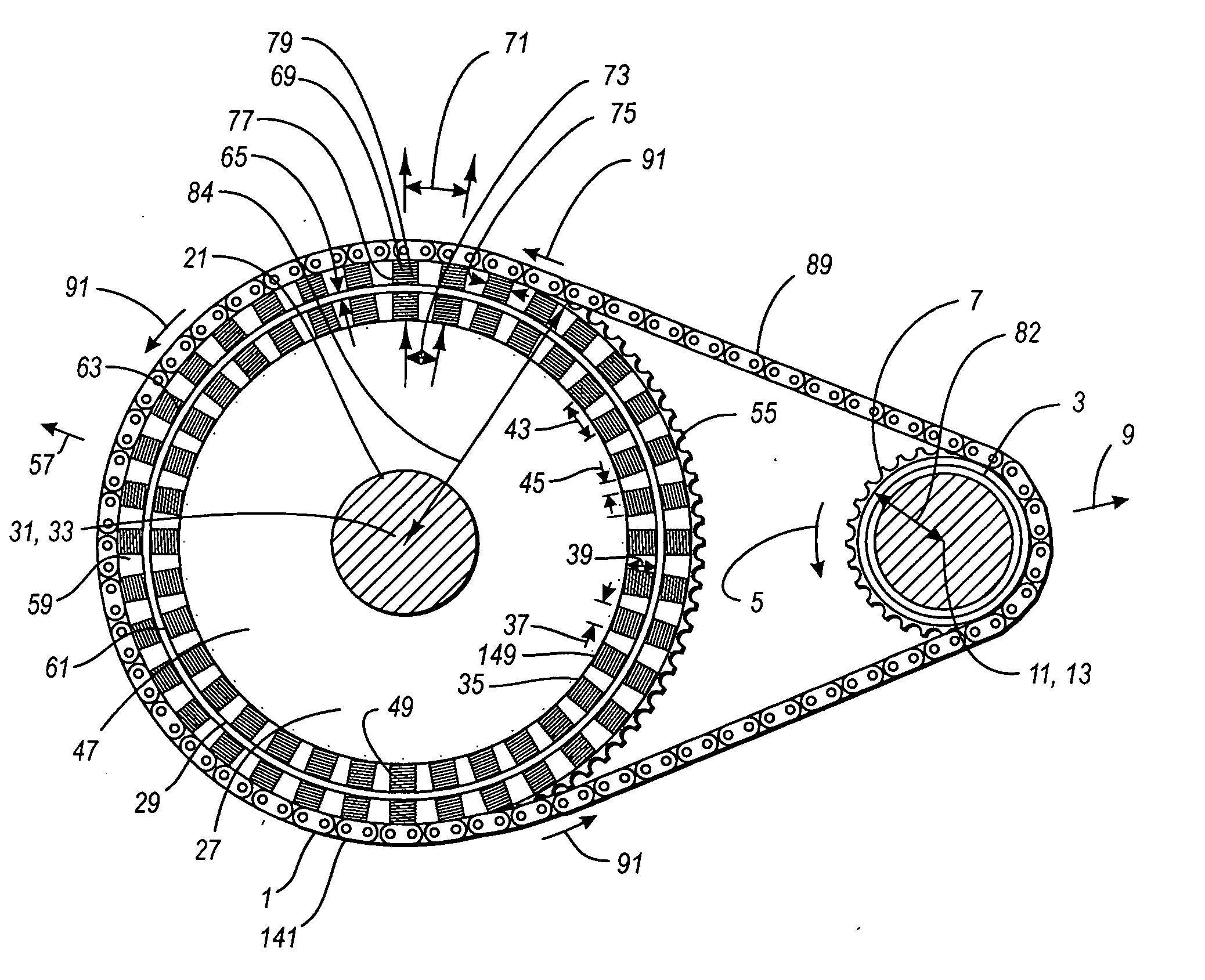
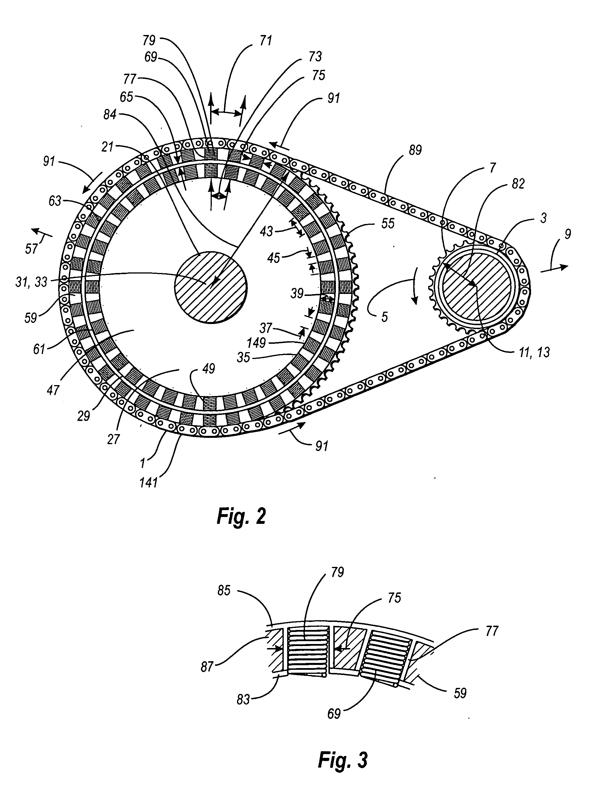
[0012] An alternative embodiment of the gear assembly for each gear can include an input armature having a plurality of input magnetic insets such as that provided for the output armature. Each input magnetic inset has an input armature
magnet, which can be a permanent
magnet or an
electromagnet, as discussed for the output armature magnets. The magnetic elements for this embodiment are incorporated into the transfer belt, and extend from the armature inboard end to the armature outboard end. The transfer magnets are affixed in the transfer belt magnetic elements in a manner similar to that for the transfer drum magnetic elements. The magnetic elements of the transfer belt are rotatably connected by pivot pins which allows the radial rotation of the magnetic elements of the transfer belt so that they can be positioned a uniform belt spacing from the output armature periphery as they move from an disengaged position to an engaged position proximal to the output armature and as they move from a disengaged position to an engaged position proximal to the input armature. An inboard transfer belt sprocket and an outboard transfer belt sprocket are each rotatably affixed to the output shaft by an output sprocket bearing. These bearings position the sprockets longitudinally and prevent longitudinal movement of the sprockets while allowing the sprockets to rotate freely on the output shaft. The pivot pins are preferably extended to provide for them to engage the inboard transfer belt sprocket and the outboard transfer belt sprocket, these sprockets providing for maintaining uniform belt spacing when the magnetic elements are in an engaged position and allow separation of the magnetic elements from the output armature as the magnetic elements move to a disengaged position. Similarly an inboard input sprocket and an outboard input sprocket provide for maintaining uniform belt spacing for the input armature. Each of these sprockets is connected to the input shaft by an input sprocket bearing which positions the sprocket longitudinally and prevents longitudinal movement of the sprocket while allowing the sprocket to rotate freely on the input shaft.
[0013] A further alternative embodiment of the gear assembly incorporates an inboard input sprocket and an outboard input sprocket which are rigidly attached to the input shaft, thereby eliminating the need for the input armatures. For that embodiment, the transfer belt is magnetically engaged only to the output armature when the gear assembly is selected and activated. When the gear assembly is not activated the transfer belt runs continually with the input shaft with no
energy transfer to the output armature occurring. The inboard transfer belt sprocket, the outboard transfer belt sprocket, the inboard input sprocket and the outboard input sprocket are separated from the respective armature by an armature sprocket spacing.
[0017] The magnetic elements can be energized and de-energized in a controlled sequence, to promote smoothness of changing gears or speeds. The power to the transfer magnets of some or all of the engaged magnetic elements can be ramped up and ramped down in order to provide a more smooth change of speeds or gears. To provide for smoothness of shifting gears, the transfer magnets of the selected gear assembly can be energized or ramped up over a selected time period, while the de-selected gear assembly is de-energized or ramped down over a selected time period. Other shifting control means will be known to persons skilled in the art for providing a more smooth change of speeds or gears.

