System and method for intrusion detection using a time domain radar array

a time domain radar and array technology, applied in the field of radar motion detection, can solve the problems of low accuracy, lower false alarm rate, and inapplicability of conventional narrowband radars arranged in sparse arrays, so as to improve performance, improve angle and range resolution, and improve the effect of selection

Inactive Publication Date: 2007-08-09
HUMATICS CORP
View PDF10 Cites 15 Cited by
  • Summary
  • Abstract
  • Description
  • Claims
  • Application Information

AI Technical Summary

Benefits of technology

[0010] An advantage of the current invention is that ultra wideband (UWB) pulses are used. As used herein, UWB refers to very short RF pulses of low duty cycle ideally approaching a Gaussian Monocycle. Typically these pulses have a relative bandwidth (i.e., signal bandwidth / center frequency) which is greater than 25%. The ultra wideband nature of these pulses improves both angle and range resolution, which results in improved performance (e.g., greater selectivity, more sensitive motion detection). The term “wavelength”, as used herein in conjunction with ultra wideband systems, refers to the wavelength corresponding to the center frequency of the ultra wideband pulse.
[0011] Another advantage of the current invention is that high resolution radar images are formed which give an accurate picture of the inside of the building and the surrounding area. The current invention uses this image to, among other things, detect motion in a highly selective manner and to track moving objects within the building and the surrounding area. High resolution radar images are possible because the TM-UWB radars positioned around the perimeter of the building form a sparse array capable of achieving high angular resolution. Angular resolution is a function of the width of the TM-UWB radar array, i.e., the wider the array, the greater the angular resolution. Conventional narrowband radars arranged in a sparse array suffer off-axis ambiguities, and are therefore not practical. However, the UWB pulses transmitted by the TM-UWB radars are sufficiently short in duration (with very few sidelobes) that the radars can be used in a sparse array configuration without off-axis ambiguities. Furthermore, range ambiguities are cured by time-encoding the sequence of transmitted TM-UWB pulses.
[0012] Another advantage of the current invention is that highly selective motion detection is possible. Using the high resolution radar images generated by the TM-UWB radar array, motion can be distinguished based on criteria appropriate to the environment in which the intrusion detection system operates. For example, home security systems according to the present invention can distinguish outside movement around doors and windows from movement inside the house. Alternatively, business security systems can distinguish movement in an unsecured portion of the building from movement in a secured portion. This selectivity can result in lower false alarm rates.
[0013] Another advantage of the current invention is that high angular resolution may be achieved at a low center frequency. Because the transmitted UWB pulses have a large relative bandwidth, and because the radar array is wide, a lower center frequency can be maintained and still achieve a high angular resolution. Operating at a lower center frequency relaxes the timing requirements of the system, which makes it easier to achieve synchronization between the radars, and results in less complex, less expensive implementations. A low center frequency also results in UWB pulses that are able to better penetrate lossy materials and withstand weather effects.

Problems solved by technology

Conventional narrowband radars arranged in a sparse array suffer off-axis ambiguities, and are therefore not practical.
This selectivity can result in lower false alarm rates.

Method used


Image

  • System and method for intrusion detection using a time domain radar array
  • System and method for intrusion detection using a time domain radar array
  • System and method for intrusion detection using a time domain radar array

Examples


first embodiment

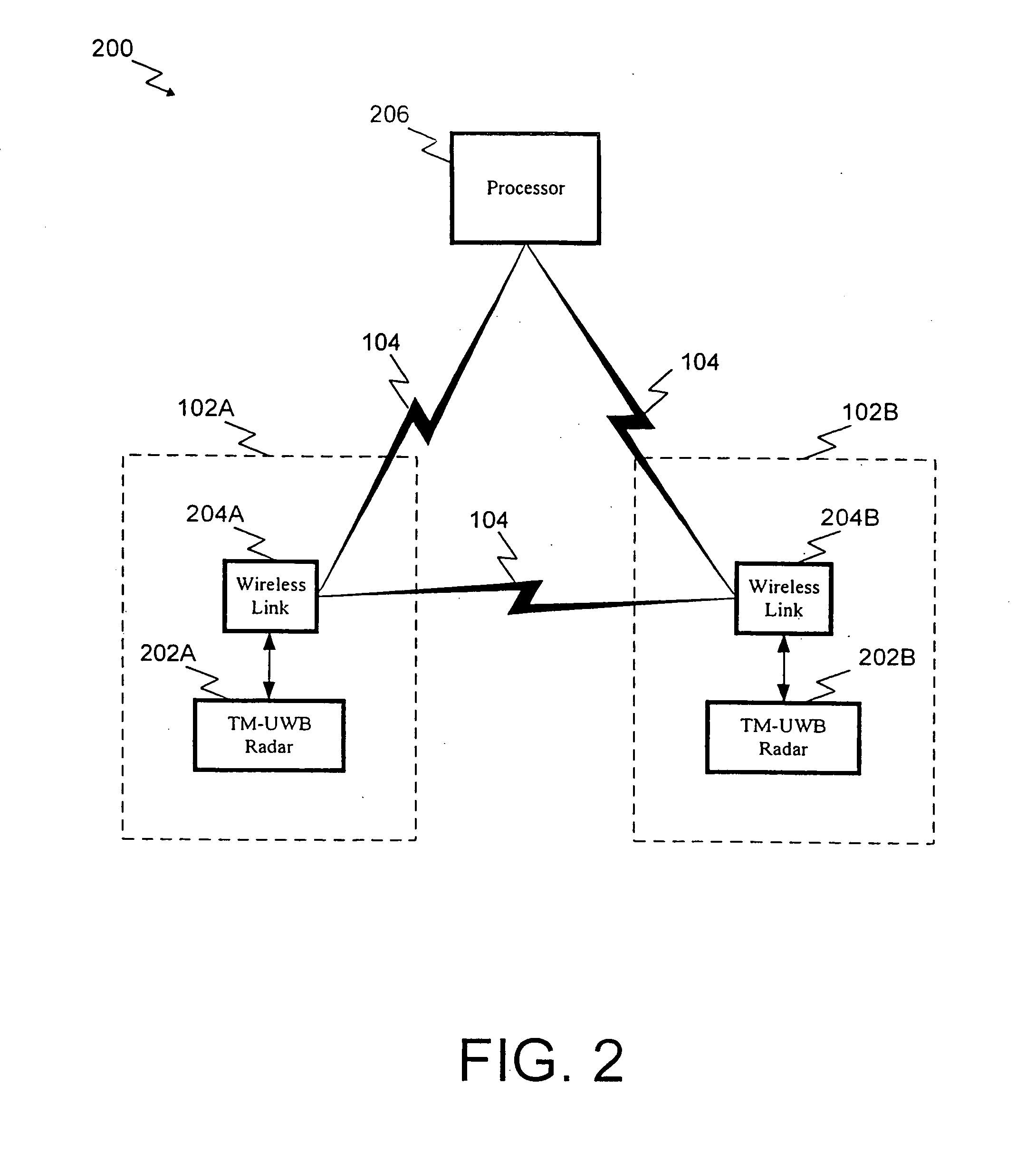
[0055] Synchronizing radars 202 can be accomplished in at least two different ways. In a first embodiment, a synchronization signal is transmitted between radars 202 via wireless links 204. In this embodiment, wireless links 204 are chosen which have high temporal resolution, on the order of ten picoseconds. This resolution is necessary to achieve the desired synchronization.

second embodiment

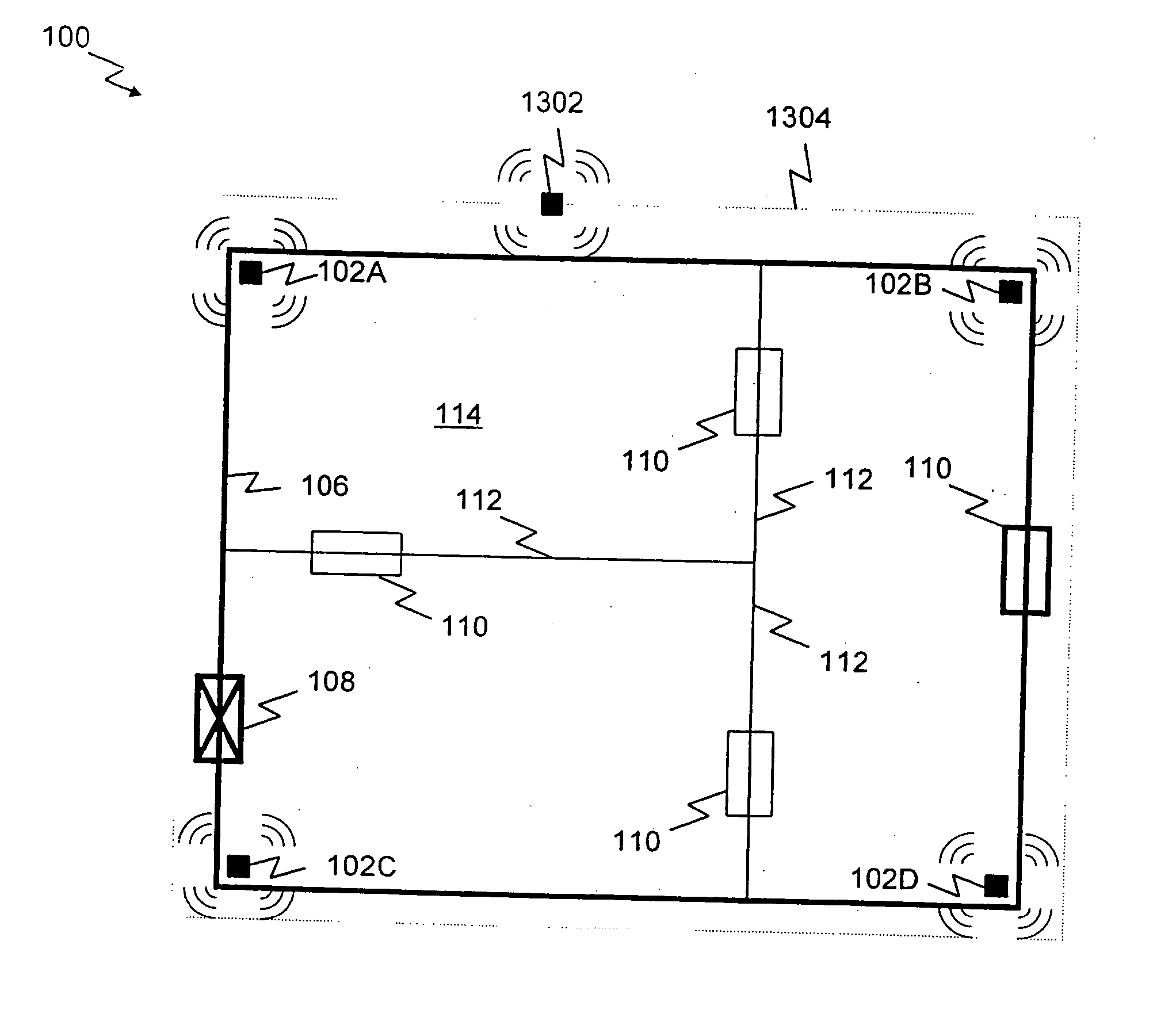
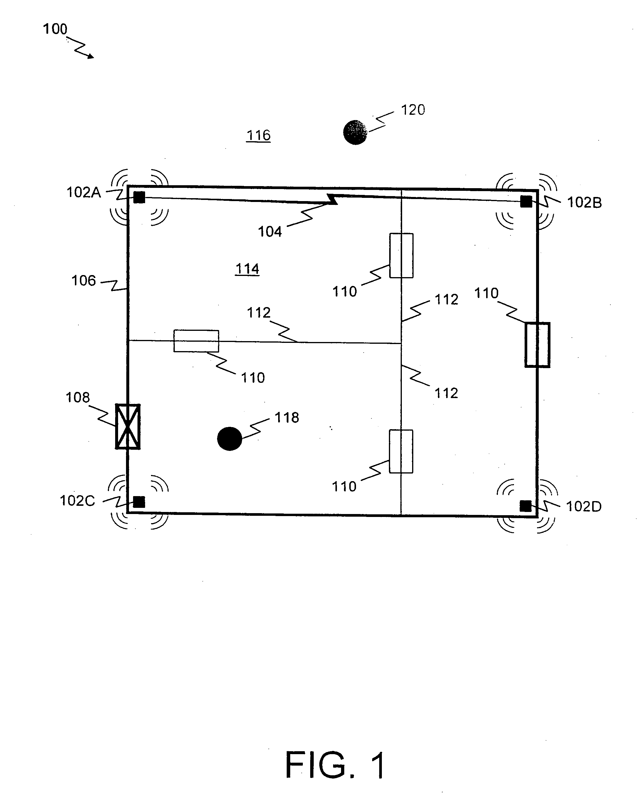
[0056] In a second embodiment, each radar 202 receives UWB pulses transmitted by the radar 202B via two paths. As described above, radar 202A receives forward scattering signal returns that reflect off reflective body 502. However, radar 202A can also receive UWB pulses that travel directly from radar 202B to radar 202A. These UWB pulses can be used by radar 202A for synchronization, so long as the distance between the radars is known. Those skilled in the art will recognize that the antenna 208B associated with radar 202B must be chosen such that its beam pattern provides for sufficient transmission in the direction of radar 202A.

[0057]FIG. 6 depicts intrusion detection system 200 operating in a second mode. In this mode, certain of the radars 202 are used for forward scattering purposes only, i.e., they transmit UWB pulses which are received by other radars 202, but do not themselves receive any signal returns. For example, in FIG. 6, radar 202B transmits UWB pulses that are recei...


PUM


Abstract

A system and method for highly selective intrusion detection using a sparse array of time modulated ultra wideband (TM-UWB) radars. Two or more TM-UWB radars are arranged in a sparse array around the perimeter of a building. Each TM-UWB radar transmits ultra wideband pulses that illuminate the building and the surrounding area. Signal return data is processed to determine, among other things, whether an alarm condition has been triggered. High resolution radar images are formed that give an accurate picture of the inside of the building and the surrounding area. This image is used to detect motion in a highly selective manner and to track moving objects within the building and the surrounding area. Motion can be distinguished based on criteria appropriate to the environment in which the intrusion detection system operates.

Description

RELATED APPLICATIONS [0001] This application is a continuation of U.S. patent application Ser. No. 09 / 767,131, filed Jan. 23, 2001 (issued as U.S. Pat. No. 6,400,307), which is a continuation of U.S. application Ser. No. 09 / 332,502, filed Jun. 14, 1999 (issued as U.S. Pat. No. 6,177,903). This application is related to U.S. patent application Ser. No. 09 / 332,503 (issued as U.S. Pat. No. 6,218,979), entitled “Wide Area Time Domain Radar Array”, which is incorporated herein by reference.BACKGROUND OF THE INVENTION [0002] 1. Field of the Invention [0003] The present invention relates generally to radar motion detection, and more particularly to using a sparse array of time modulated ultra wideband radars for highly selective intrusion detection. [0004] 2. Related Art [0005] Today, many homes and businesses employ surveillance systems for intrusion detection. Consumers have spent billions of dollars on home security systems over the last few years, and the number of homes with security ...

Claims


Application Information

Patent Timeline
Patent Type & Authority Applications(United States)
IPC IPC(8): G01S13/62G01S13/02G01S13/04G01S13/88G01S13/89
CPCG01S7/003G01S7/4004G01S13/0209G01S13/04G01S13/56G08B13/1636G01S13/878G01S13/88G01S13/888G01S13/89G01S13/87
Inventor FULLERTON, LARRY W.RICHARDS, JAMES L.
Owner HUMATICS CORP
Why Eureka
Try Eureka