Image processing apparatus

a technology of image processing and apparatus, applied in the direction of digital output to print units, instruments, digital computer details, etc., can solve the problem of insufficient power saving and achieve the effect of reducing power consumption

Inactive Publication Date: 2007-08-09
SHARP KK
View PDF9 Cites 26 Cited by
  • Summary
  • Abstract
  • Description
  • Claims
  • Application Information

AI Technical Summary

Benefits of technology

[0009] The object of the present invention is to provide an image processing apparatus that can reduce power consumption as compared to the conventional case by energizing required minimum devices at an appropriate timing depending on contents of a request received from an external apparatus through a communicating medium during a power-saving state.

Problems solved by technology

However, when an apparatus is in a power-saving state and some sort of process is requested by an external apparatus through a communicating medium, if energization is always started for many non-energized devices due to the request to perform the requested process, it is problematic that sufficient power-saving cannot be achieved.

Method used


Image

  • Image processing apparatus
  • Image processing apparatus
  • Image processing apparatus

Examples


first embodiment

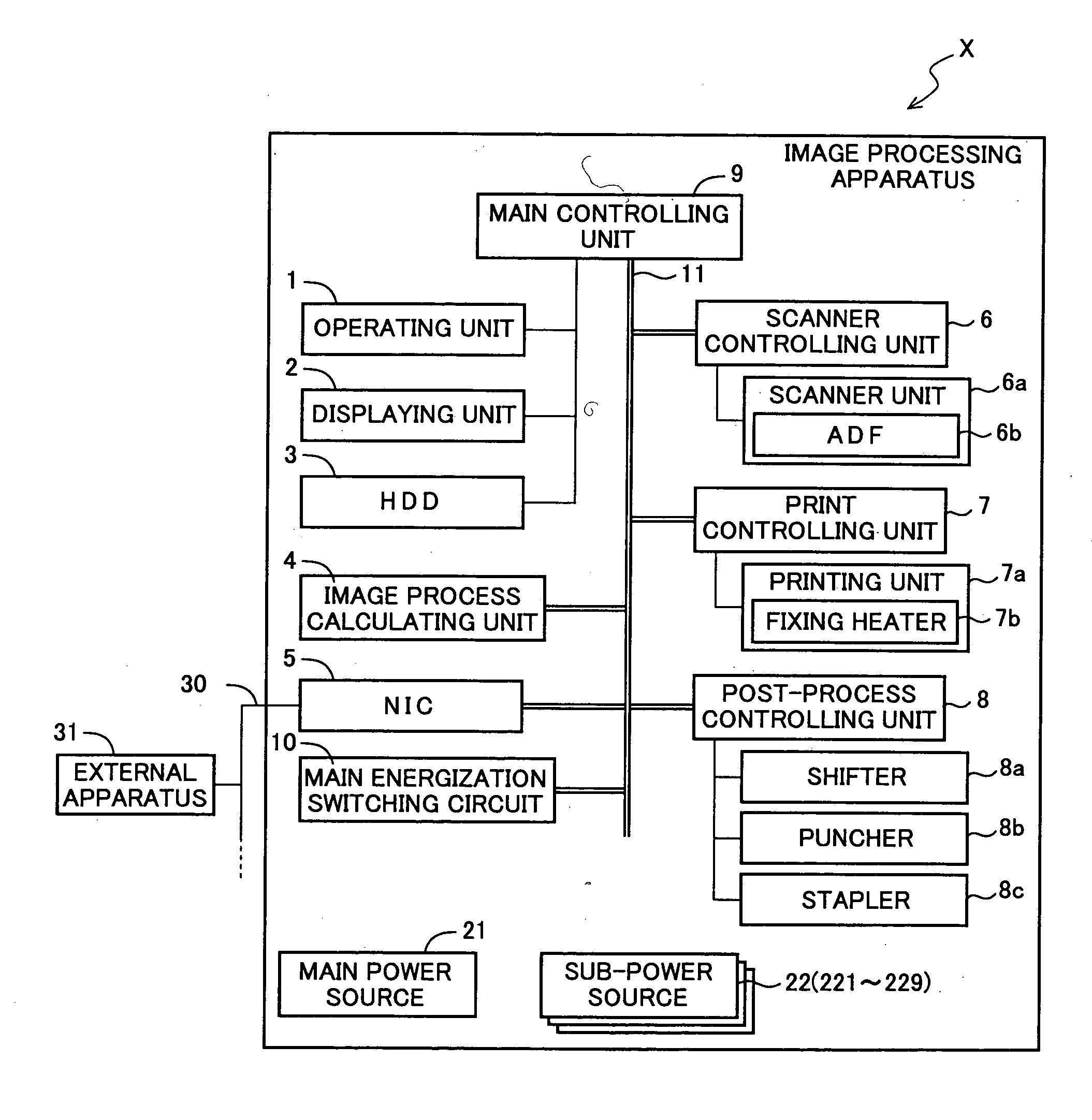
[0244] By the way, as shown in the power source system diagram of FIG. 4, in the power-source connection relationships for the function blocks, the controlling portion switching the energization state of each function block in the hierarchical energization controlling process is configured in a distributed manner as the first energization control executing unit of the NIC 5 and the second energization control executing unit of the controlling units 6 to 9.

[0245] However, in some embodiments, the hierarchical energization controlling process may be executed by performing the energization control for all the function blocks 3, 6 to 9, 6a, 7a, 8a to 8c with the NIC 5, which is energized even during the sleep mode.

[0246]FIG. 11 is a power source system diagram of a second embodiment of power-source connection relationships in the image processing apparatus X. In the image processing apparatus X including the configuration of the second embodiment, the NIC 5 performs the hierarchical en...

second embodiment

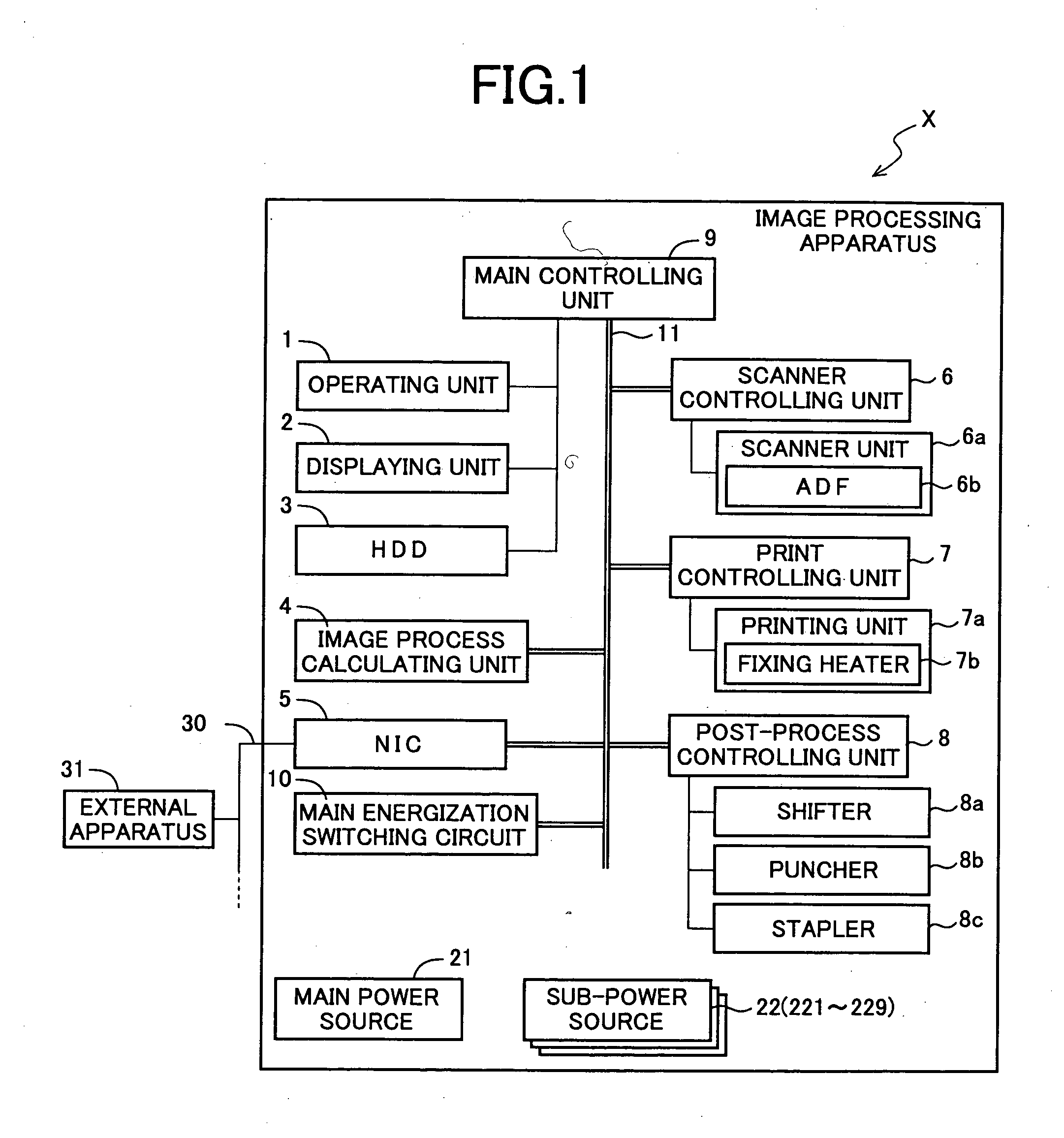
[0248] In the case of the second embodiment, the MPU 53 of the NIC 5 executes a predetermined control program to perform the energization control for the first sub-power source 221 to the ninth sub-power source 229 in accordance with the control rule shown in FIGS. 9 to 10. In this case, the NIC 5 acts as the entire function that performs the energization control for the function blocks.

[0249] Such a configuration also is one embodiment of the present invention.

[0250] The present invention is applicable to an image processing apparatus.

[0251] As described above, according to the present invention, it is controlled whether energization is individually performed for each of a plurality of function blocks sectionalized in accordance with each function, and only the required minimum function blocks can be controlled to become the energized state depending on the contents of the data processing request received from an external apparatus through a communicating medium when an image pro...


PUM


Abstract

To provide an image processing apparatus that can reduce power consumption as compared to a conventional case by energizing required minimum devices at an appropriate timing depending on contents of a request received from an external apparatus through a communicating medium during a power-saving state, if a data processing request is received from the external apparatus through a NIC during a sleep mode, an MPU of the NIC and an MPU of each controlling unit control automatic changeover switches, which switch energization states of sub-power sources, to control energization of each function block based on contents of the data processing request and the state of the own apparatus. When switching the function blocks from a “non-energized state” to an “energized state”, a hierarchical energization controlling process is performed to switch the functional blocks with hierarchical relationships to the “energized state” in the order from higher to lower blocks.

Description

[0001] This Non-provisional application claims priority under 35 U.S.C. §119 (a) on Patent Application No. 2006-027229 filed in JAPAN on Feb. 3, 2006, the entire contents of which are hereby incorporated herein by reference. FIELD OF THE INVENTION [0002] The present invention relates generally to an image processing apparatus including a communicating medium that communicates with an external apparatus, and more particularly, to an image processing apparatus that is preferable for power saving. BACKGROUND OF THE INVENTION [0003] Generally, an image processing apparatus, such as a multifunctional peripheral (MFP) including a printer, scanner, facsimile machine, and copier or functions thereof, includes a communicating medium (such as a NIC (Network Interface Card) or modem (Modulator-Demodulator)) that communicates with an external apparatus (such as a computer or other image processing apparatuses) through a communication medium such as a network or telephone lines. Some of such ima...

Claims


Application Information

Patent Timeline
Patent Type & Authority Applications(United States)
IPC IPC(8): H02H3/00
CPCG03G15/5004H04N1/00885H04N1/00891H04N2201/0094H04N1/00904H04N1/00928H04N1/00896
Inventor OKADA, TADASHI
Owner SHARP KK
Why Eureka
Try Eureka