
Memory card and memory card system

a memory card and memory card technology, applied in the field of memory cards, can solve the problems of not having a spec generated, not guaranteeing the system for a high-speed recording of the conventional memory card cannot guarantee so as to achieve the lowest recording rate, guarantee the speed of writing data into the flash memory, and guarantee the effect of the lowest recording ra

Active Publication Date: 2007-08-09
PANASONIC CORP
View PDF6 Cites 33 Cited by
  • Summary
  • Abstract
  • Description
  • Claims
  • Application Information

AI Technical Summary

Benefits of technology

[0039] The memory card that has above structure can judge whether the write block size that is a size of data which the host apparatus records and is specified by the write command satisfies a predetermined condition to guarantee a certain lowest recording rate, and can perform a control operation concerning whether to permit writing of data. When the write block size does not satisfy the predetermined condition, the memory card sends a response to inform an error against the write command and does not execute writing of data. Therefore, if the memory card is used to record data sequentially by a plurality of different host apparatuses, it is possible to guarantee the lowest recording rate.
[0050] With this arrangement, the host apparatus can obtain the buffer memory capacity data from the memory card, and in a case where the host apparatus need to write data continuously to the memory card at the lowest recording rate, it is possible to adjust a capacity of the buffer memory. The buffer memory is effective in guaranteeing a certain recording rate when a recording rate fluctuation of the memory card and an error retry are taken into account.

Problems solved by technology

However, the system for a high-speed recording of the conventional memory card cannot guarantee a lowest limit of the recording rate (hereafter referred to as the “lowest recording rate”) as a recording speed of the memory card.
However, this memory card does not have a spec generated taking into account a variation in flash memories, and does not guarantee the lowest recording rate.
The following explains why it is difficult for the conventional system for a high-speed recording to guarantee the lowest recording rate.
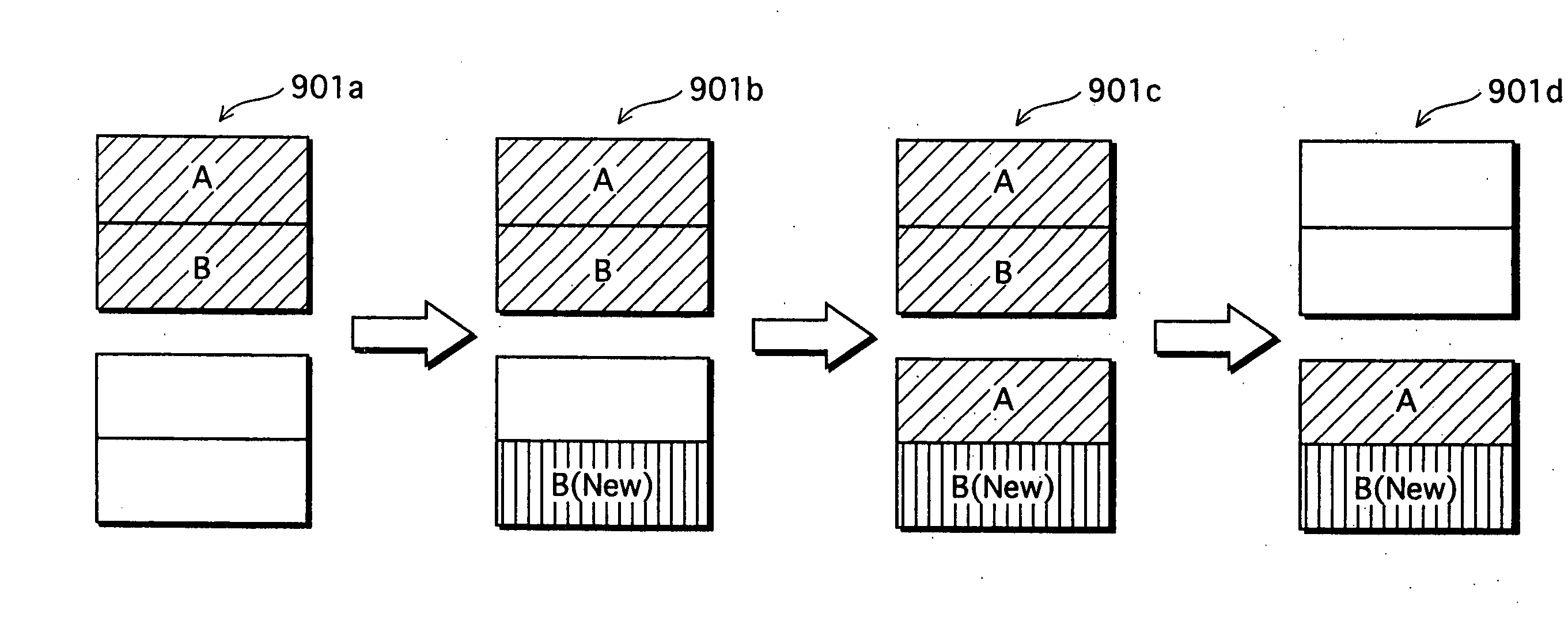
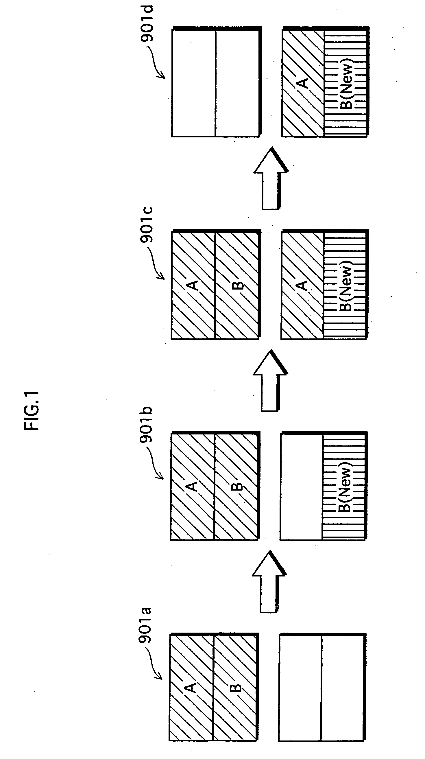
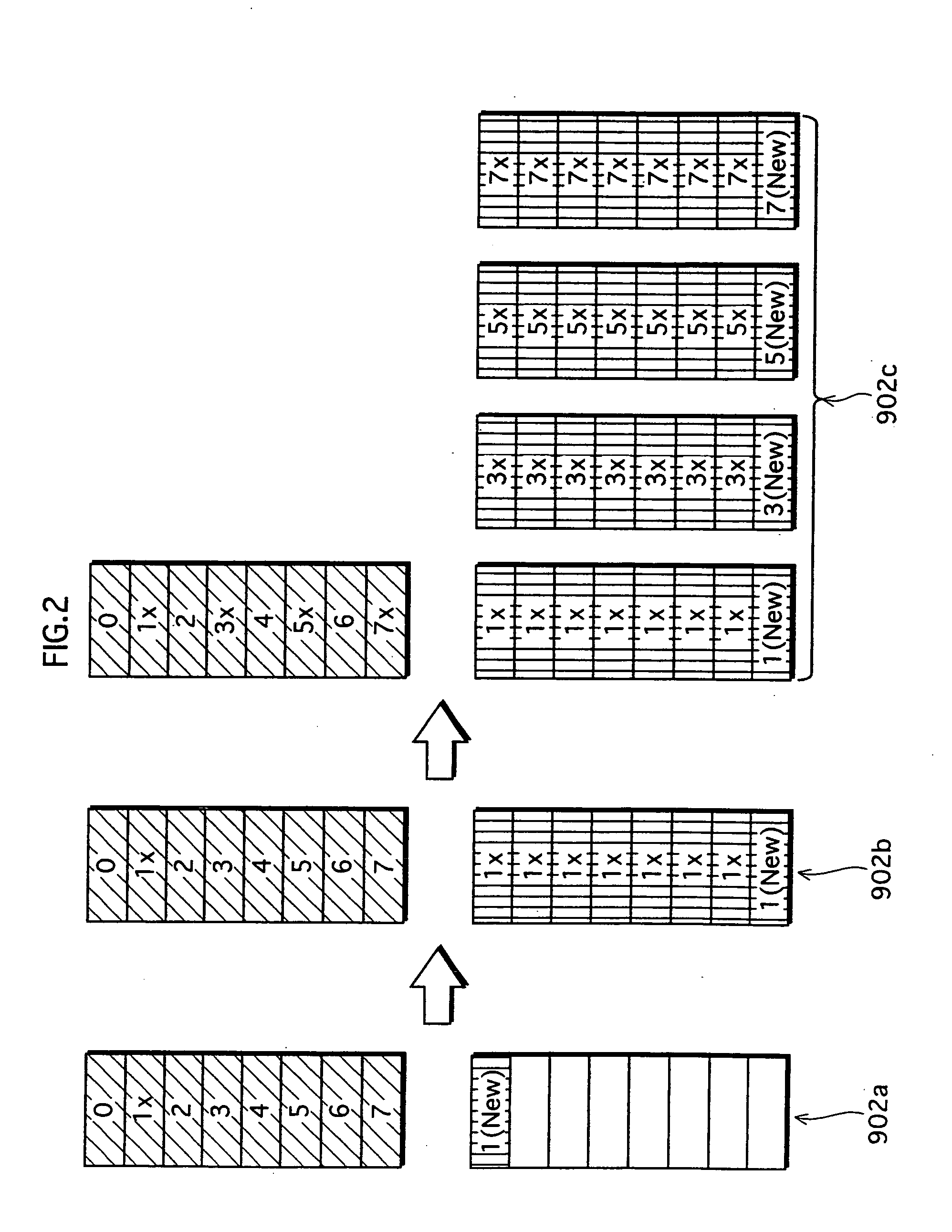
For example, in a case where the host apparatus writes data in units of erase blocks into the memory card in which data has been written in units of sectors by a PC, it is likely that the empty block search occurs and a recording rate of the memory card diminishes.
This makes it difficult to guarantee the lowest recording rate of the memory card.

Method used


Image

  • Memory card and memory card system
  • Memory card and memory card system
  • Memory card and memory card system

Examples


first embodiment

[0087] The following describes a memory card of the first embodiment according to the present invention.

[0088]FIG. 4 shows a general structure of a memory card of the first embodiment.

[0089] Here, in the FIG. 4, thick arrows show the flow of data from a host apparatus to be recorded into a memory card 20, and thin arrows show the flow of control signal or control data.

[0090] As shown in the FIG. 4, the memory card 20 comprises an external interface unit 1, a command analyzing unit 2, a controlling unit 3, a flash memory 6, and a ROM (Read Only Memory) 19 that includes a writable block size storage area 7, a guaranteed write rate storage area 8, and a buffer memory capacity storage area 9.

[0091] Here, the external interface unit 1 receives a command from a host apparatus and sends, to the host apparatus, a response against the command issued by the host apparatus. The external interface unit 1 also transfers data.

[0092] The command analyzing unit 2 analyzes the command received ...

second embodiment

[0150] The following explains a memory card system according to the second embodiment of the present invention.

[0151]FIG. 9 shows a general structure of a memory card system according to the second embodiment.

[0152] As shown in FIG. 9, the memory card system composed of the memory card 20 described in the first embodiment and a host apparatus 21 that records data into the memory card. Here the explanation is provided on a case where a camera recorder is used as the host apparatus 21.

[0153] The host apparatus 21 includes an image data input unit 10, a compressing unit 11, a buffer memory 12, a read-modify-write unit 13, and a controlling unit 14.

[0154] The image data input unit 10 is where digital image data is input.

[0155] The compressing unit 11 compresses the image data that is input through the image data input unit 10.

[0156] The buffer memory 12 temporarily stores the image data.

[0157] The read-modify-write unit 13 records the data read from the buffer memory 12 into the ...

third embodiment

[0170] The following explains a memory card 30 that is generated by partly deforming the memory card 20 of the first embodiment.

[0171] The memory card 20 divides, to prevent a recording rate from becoming lower than a predetermined rate, data into writable block sizes which are integral multiples of an erase block and accepts writings of data from the host apparatus only in units of integral multiples of the writable block sizes, and regards other writings as errors. Therefore, the host apparatus has a function to read the writable block size 7 stored in the ROM 19. On the other hand, a memory card 30 stores the writable block size not in the ROM 19 but in a nonvolatile re-writable memory that is different from the flash memory 6, and updates the writable block size under given conditions.

[0172]FIG. 11 shows a general structure of the memory card 30 according to the third embodiment. Here, in FIG. 11, components of the memory card 30 according to the present embodiment that are th...


PUM


Abstract

A memory card is equipped in a host apparatus and used for data recording. The memory card has a built-in flash memory and an internal ROM, there is prestored a predetermined writable block size corresponding to a certain integral multiple of a size of an erase block. A write block size of a write command issued by the host apparatus. The data size is detected and compared to the writable block size, so as to decide whether the write block size is an integral multiple of the writable block size, thereby judging whether write is permitted. Only when the write is permitted, data is written from the host apparatus into the memory card. If the write is not permitted, a response to inform an error is returned to the host apparatus.

Description

TECHNICAL FIELD [0001] The present invention relates to a memory card including a flash memory, and a memory card system for recording data into the memory card. BACKGROUND ART [0002] Memory cards that are card-type recording media including a flash memory, such as SD (Secure Digital) cards, are subminiature and ultraslim. Therefore, with its convenience in handling being appreciated, memory cards are widely used in digital apparatuses such as digital cameras to record data. For example, memory cards are used as recording media for recording moving images of relatively low transmission rate such as MPEG4 (Moving Picture Experts Group 4). [0003] A flash memory included in aforementioned memory card generally comprises a plurality of blocks of a predetermined size (hereafter referred to as the “erase block”) each of which to be the minimum unit to erase recorded data. When erasing data, an erasing process is performed in units of the erase block. The erase block comprises a plurality ...

Claims


Application Information

Patent Timeline
Patent Type & Authority Applications(United States)
IPC IPC(8): G11C16/04G06F3/06G06F12/00G06F12/14G06K19/07
CPCG06F3/0622G06F3/0623G06F3/0661G06K19/07732G06F12/1433G06F2212/2022G06K19/07G06F3/0679G06F3/06G06F12/00
Inventor OTSUKA, TAKESHIOHTA, HARUO
Owner PANASONIC CORP
Learn More