Objective lens driving unit and optical pickup device having the same

a driving unit and optical pickup technology, applied in the direction of optical recording heads, instruments, data recording, etc., can solve the problems of generating coma aberration that is different from the spherical aberration described above, and reducing the accuracy of recording or reproducing information by the optical pickup device. , to achieve the effect of reducing the shift of position, and reducing the loss o

Inactive Publication Date: 2007-08-09
FUNAI ELECTRIC CO LTD
View PDF3 Cites 4 Cited by
  • Summary
  • Abstract
  • Description
  • Claims
  • Application Information

AI Technical Summary

Benefits of technology

[0019]According to the first structure of the present invention, the injection hole for injecting adhesive for fixing the liquid crystal element is provided to the movable holder. Therefore, when the optical axis of the objective lens and the center axis of the liquid crystal element are aligned, it is possible to project a light beam to the objective lens and the liquid crystal element for adjustment, to search a position where the coma aberration becomes minimum while moving the liquid crystal element, and to inject adhesive from the injection hole so as to fix the liquid crystal element when a optimal position is found. Therefore, it is unnecessary to perform adjustment of relative position between the optical axis of the objective lens and the center axis of the liquid crystal element while viewing the liquid crystal element as well as a marker for positioning provided to the liquid crystal element, and the positioning can be performed easily and precisely. In addition, since the positioning can be performed while measuring a position where the coma aberration becomes minimum as described above, it is possible to measure the coma aberration also during a period while the adhesive is being cured so that fine adjustment of a position of the liquid crystal element can be performed before the adhesive is cured completely. Thus, it is possible to relieve a shift of position due to contraction of the adhesive.
[0020]In addition, according to the second structure of the present invention, in the objective lens driving unit having the first structure described above, it is possible to dispose the injection hole at a position that the liquid crystal element can be fixed easily, because the disposed injection hole is provided to the side face of the movable holder.
[0021]In addition, according to the third structure of the present invention, in the objective lens driving unit having the second structure described above, it is possible to form the injection hole easily. In addition, UV cure adhesive for fixing the liquid crystal element to the movable holder can be cured by projecting ultraviolet rays into the injection hole. Therefore, the work of fixing the liquid crystal element at the correct position can be performed easily.
[0022]In addition, according to the fourth structure of the present invention, the optical pickup device equipped with the objective lens driving unit having any one of the first to the third structures described above can adjust relative position precisely between the optical axis of the objective lens and the center axis of the liquid crystal element disposed for aberration correction. Therefore, it is possible to maintain high performance of the optical pickup in recording and reproducing information, so that reliability of the device can be improved.
[0023]In addition, according to the fifth structure of the present invention, the movable holder is provided with an injection hole for injecting adhesive for fixing the liquid crystal element. Therefore, when the optical axis of the objective lens and the center axis of the liquid crystal element are aligned, it is possible to project a light beam to the objective lens and the liquid crystal element for adjustment, to search a position where the coma aberration becomes minimum while moving the liquid crystal element, and to inject adhesive from the injection hole so as to fix the liquid crystal element when a optimal position is found. Therefore, it is unnecessary to perform adjustment of relative position between the optical axis of the objective lens and the center axis of the liquid crystal element while viewing the liquid crystal element as well as a marker for positioning provided to the liquid crystal element, and the positioning can be performed easily and precisely.
[0024]In addition, since the positioning can be performed while measuring a position where the coma aberration becomes minimum as described above, it is possible to measure the coma aberration also during a period while the adhesive is being cured so that fine adjustment of a position of the liquid crystal element can be performed before the adhesive is cured completely. Thus, it is possible to relieve a shift of position due to contraction of the adhesive. In addition, since the injection hole is provided to the side face of the movable holder and the injection hole is a bore extending in the direction substantially perpendicular to the optical axis of the objective lens, the injection hole can be formed easily. Furthermore, the liquid crystal element can be fixed easily. Therefore, positioning between the optical axis of the objective lens and the center axis of the liquid crystal element that is disposed for aberration correction can be performed precisely, so that the optical pickup can record and reproduce information correctly. Thus, the optical pickup device of the present invention can obtain high reliability.

Problems solved by technology

As a result, there may be a problem that accuracy in recording or reproducing information by the optical pickup device is lowered.
As a result, there may be a problem that coma aberration that is different from the spherical aberration described above will be generated when a voltage is applied to the liquid crystal element.
However, also in the case described above, if the center axis of the liquid crystal element is shifted from the optical axis of the objective lens due to insufficient adjustment in the assembling process, the coma aberration is generated.
However, in the structure described in JP-A-2002-237077 or JP-A-2005-71457, there is a problem that relative position between the center axis of the liquid crystal element and the optical axis of the objective lens cannot be adjusted precisely because of variation of machining accuracy of the position markers with respect to the center axis of the liquid crystal element and the optical axis of the objective lens.
In addition, there is also a problem that precise positioning cannot be performed sufficiently because that a magnification of a CCD (a slid-state image sensing device) camera cannot be set to a large value when the CCD camera is used for viewing the position markers for adjusting relative position between the liquid crystal element and the objective lens, since it is necessary to view a plurality of position markers at the same time.
In addition, there is also a problem that attachment work of the liquid crystal element to a movable holder is difficult because that liquid crystal element can hardly seen by the CCD camera when a highly transparent electrodes are used for improving quality in reading information.
In addition, there is also a problem that the liquid crystal element is shifted from the position before being adhered due to contraction of adhesive if the liquid crystal element is fixed by using the adhesive.

Method used


Image

  • Objective lens driving unit and optical pickup device having the same
  • Objective lens driving unit and optical pickup device having the same
  • Objective lens driving unit and optical pickup device having the same

Examples


Embodiment Construction

[0032]Now, an embodiment of the present invention will be described with reference to the attached drawings. At this point the embodiment described below is merely an example, and the present invention is not limited to this embodiment.

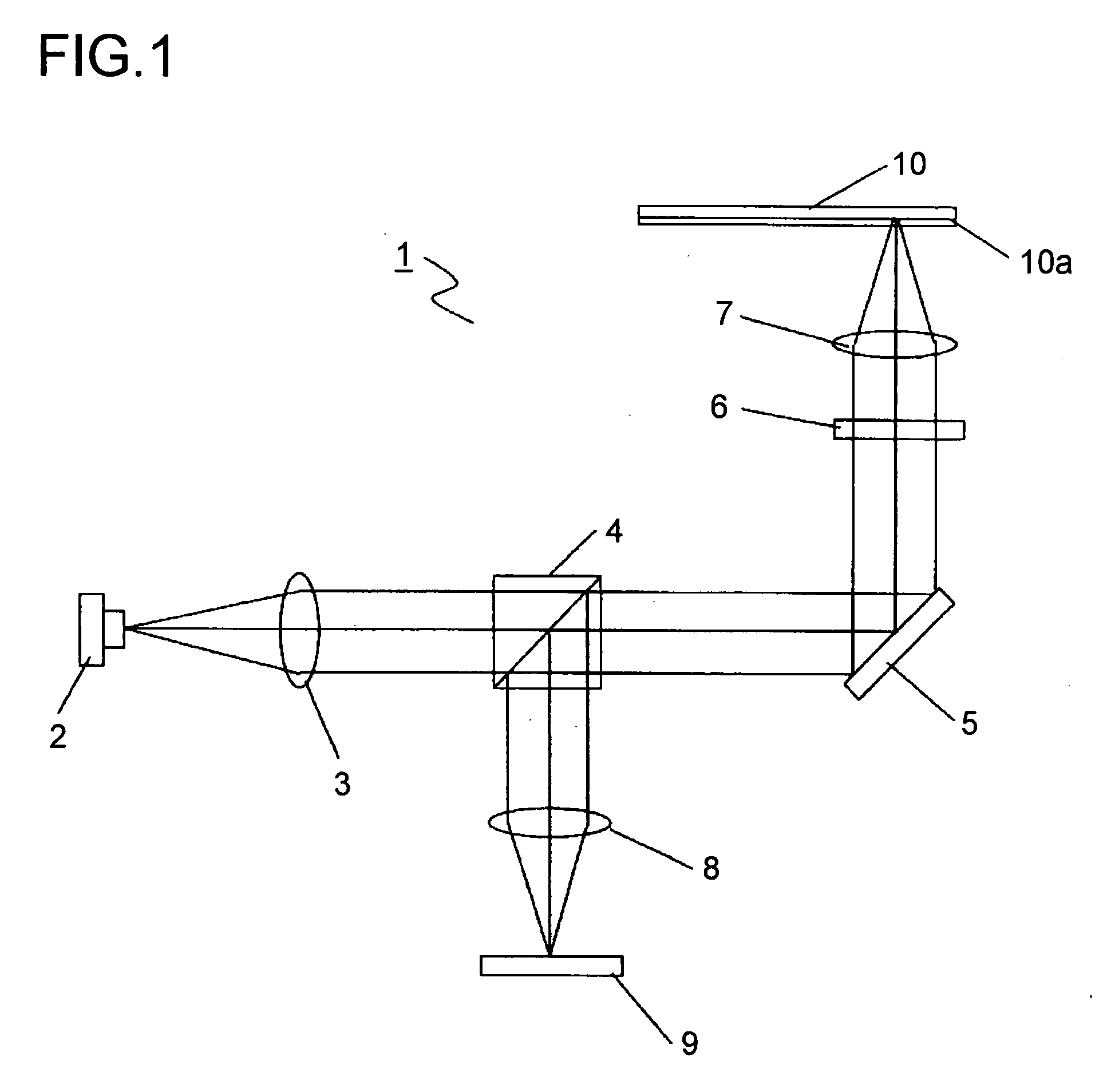
[0033]FIG. 1 is a schematic diagram to show a structure of an optical system of an optical pickup device equipped with an objective lens driving unit of the present invention. In FIG. 1, numeral 1 denotes the optical pickup device that projects a light beam to an optical recording medium 10 such as, for example, a CD or a DVD and receives a reflection light from it for reading information recorded on a recording surface 10a of the optical recording medium 10. It also projects a light beam to the optical recording medium 10 for writing information on the recording surface 10a. The optical system of the optical pickup device 1 is equipped with a light source 2, a collimator lens 3, a beam splitter 4, an upstand mirror 5, a liquid crystal element 6, an o...


PUM

PropertyMeasurementUnit
thicknessaaaaaaaaaa
wavelengthaaaaaaaaaa

Abstract

The movable holder of the objective lens driving unit is provided with an opening hole. An objective lens retaining portion for retaining an objective lens is disposed at the upper portion of the opening hole, while a liquid crystal element retaining portion for retaining a liquid crystal element is disposed at the lower portion of the opening hole. The movable holder is further provided with a bore that extends from the side face of the movable holder in the direction substantially perpendicular to the optical axis of the objective lens and reaches a side face 6b of the liquid crystal element retained by the liquid crystal element retaining portion so that adhesive can be injected from the bore.

Description

[0001]This application is based on Japanese Patent Application No. 2006-030176 filed on Feb. 7, 2006, the contents of which are hereby incorporated by reference.BACKGROUND OF THE INVENTION[0002]1. Field of the Invention[0003]The present invention relates to an objective lens driving unit that is provided to an optical pickup device for projecting a light beam to an optical recording medium so that record of information or reproduction of information can be performed. In particular, the present invention relates to a structure of the objective lens driving unit that moves a liquid crystal element for correcting aberration together with an objective lens. The present invention relates also to an optical pickup device equipped with the objective lens driving unit having the devised structure.[0004]2. Description of Related Art[0005]Recently, optical recording media including a compact disc (hereinafter referred to as a CD) and a digital versatile disc (hereinafter referred to as a DVD)...

Claims


Application Information

Patent Timeline
Patent Type & Authority Applications(United States)
IPC IPC(8): G11B7/00
CPCG11B7/093G11B7/0933G11B7/1392G11B7/1369G11B7/1374G11B7/0935
Inventor TAKAHASHI, KAZUHIRO
Owner FUNAI ELECTRIC CO LTD
Why Eureka
Try Eureka