High-frequency circuit apparatus and communication apparatus using the same

a high-frequency circuit and communication apparatus technology, applied in electrical apparatus, digital transmission, time-division multiplex, etc., can solve the problems of low cost, low production cost, and difficulty in achieving small size at low cost, so as to reduce production costs and reduce production costs. , the effect of small siz

Inactive Publication Date: 2007-08-09
HITACHI MEDIA ELECTORONICS CO LTD
View PDF6 Cites 14 Cited by
  • Summary
  • Abstract
  • Description
  • Claims
  • Application Information

AI Technical Summary

Benefits of technology

[0003]In the technique as taught by JP-A-2005-210460, different signal receiving paths or channels are used in units of communication technologies, e.g., WCDMA and GSM methods. Thus, a need is felt to use an increased number of duplexers and surface acoustic wave (SAW) filters, which corresponds to the number of communication methods. This makes it difficult to downsize a high-frequency circuit apparatus (antenna common-use equipment) and reduce production costs thereof. As for the radiocommunication terminal device in its entirety, this device increases in number of parts or components required, resulting in difficulty in achievement of small size at low costs.

Problems solved by technology

This makes it difficult to downsize a high-frequency circuit apparatus (antenna common-use equipment) and reduce production costs thereof.
As for the radiocommunication terminal device in its entirety, this device increases in number of parts or components required, resulting in difficulty in achievement of small size at low costs.

Method used


Image

  • High-frequency circuit apparatus and communication apparatus using the same
  • High-frequency circuit apparatus and communication apparatus using the same
  • High-frequency circuit apparatus and communication apparatus using the same

Examples


embodiment 1

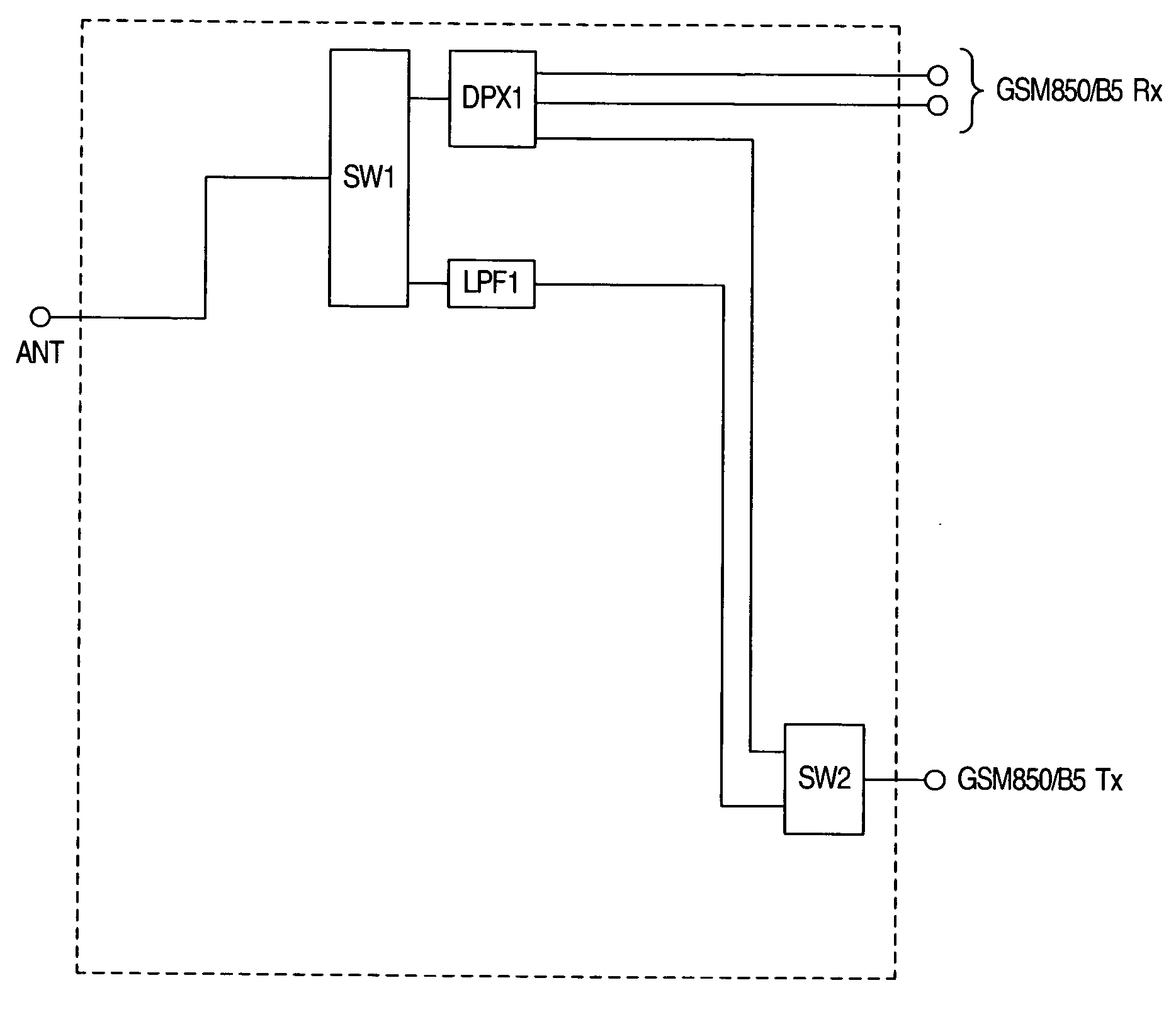
[0037]A high-frequency circuit apparatus in accordance with Embodiment 1 of this invention is shown in FIG. 1 in block diagram form. This apparatus has functional supportability to different types of communications systems, e.g., GSM850 of TDMA method, and B5 of WCDMA method. In FIG. 1, “ANT” is used to indicate an antenna terminal. A high-frequency switch SW1 switches a signal that is input from the antenna terminal ANT to a duplexer DPX1 as will be described later and switches to a signal transmission side low-pass filter LPF1, which is connected to a high-frequency switch SW2 to be later described.

[0038]The high-frequency switch SW2 performs switching between signal transmission paths in a way depending upon a presently selected communication system. More specifically, the high-frequency switch SW2 switches to either a transmission path of GSM850 or a transmission path of B5.

[0039]The duplexer DPX1 performs the wave separation and selective routing of a frequency-different signal...

embodiment 2

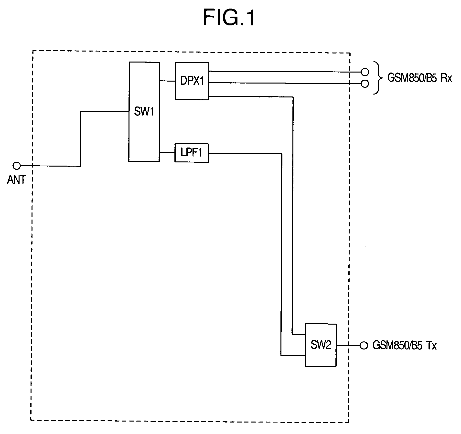
[0042]A high-frequency circuit apparatus in accordance with Embodiment 2 of the invention is depicted in FIG. 2 in block diagram form. This apparatus offers supportability to different communication systems, one of which employs the TDMA technology—e.g., GSM850, DCS—and the other of which uses the WCDMA method, such as B5.

[0043]This embodiment is similar in circuit configuration to the first embodiment stated supra, except that the former employs a diplexer (DIP) between the antenna terminal ANT and the high-frequency switch SW1.

[0044]In FIG. 2, DIP is the diplexer that is connected to the antenna terminal ANT. The diplexer DIP performs the wave separation of a signal having its frequency band of 824 MHz to 894 MHz of GSM850 as input from the antenna terminal ANT and a signal with a first frequency which is in a low frequency band including the signal of 824 MHz to 894 MHz band of B5 (Band 5) of WCDMA method and also a signal of a second frequency that is a high frequency band inclu...

embodiment 3

[0046]A high-frequency circuit apparatus in accordance with a third embodiment of the invention is shown in FIG. 3 in block diagram form. This apparatus has the supportability to a TDMA communication system, e.g., GSM850, DCS, and also to a WCDMA communication system, such as B5.

[0047]This embodiment is similar in circuit arrangement to the second embodiment of the invention, except that the former uses, in a signal path of the second frequency as wave-separated by the diplexer DIP, a high-frequency switch SW3 and a signal reception side surface acoustic wave (SAW) filter SAW1 and also a low-pass filter LPF2, which will be described below.

[0048]The high-frequency switch SW3 switches a signal of the second frequency which is in the high frequency band as has been wave-separated by the diplexer DIP to the signal-receive side SAW filter SAW1 that is connected to a DCS Rx terminal or, alternatively, switches to the diplexer DIP a sending signal which is output from the transmission side...


PUM


Abstract

A high-frequency circuit has a duplexer and a filter. The duplexer performs wave separation of send and received signals as input thereto. The filter filters the input send signal. When the send and received signals of the first modulation method are input, the send signal and the received signal of the first modulation method are wave-separated and output by the duplexer. When the received signal of the first modulation method is input, the send signal and the received signal of the first modulation method are wave-separated and output by the duplexer, and the send signal of the second modulation method is filtered by the filter.

Description

BACKGROUND OF THE INVENTION[0001]The present invention relates to a high-frequency circuit apparatus and a communications apparatus using this device.[0002]JP-A-2005-210460 discloses therein a so-called dual-support radiocommunication terminal device which has the functional supportability to a plurality of modulation methods.SUMMARY OF THE INVENTION[0003]In the technique as taught by JP-A-2005-210460, different signal receiving paths or channels are used in units of communication technologies, e.g., WCDMA and GSM methods. Thus, a need is felt to use an increased number of duplexers and surface acoustic wave (SAW) filters, which corresponds to the number of communication methods. This makes it difficult to downsize a high-frequency circuit apparatus (antenna common-use equipment) and reduce production costs thereof. As for the radiocommunication terminal device in its entirety, this device increases in number of parts or components required, resulting in difficulty in achievement of...

Claims


Application Information

Patent Timeline
Patent Type & Authority Applications(United States)
IPC IPC(8): H04L5/14H04B1/3822H04B1/40H04B1/707H04J3/02H04J13/00
CPCH03H9/725H04B1/48H04B1/006H04B1/0057
Inventor TOTSUKA, TAKAOSHIBA, TAKASHIHIKINO, OSAMU
Owner HITACHI MEDIA ELECTORONICS CO LTD
Why Eureka
Try Eureka