Laser display device

a laser display device and laser technology, applied in the direction of laser details, color television details, electrical equipment, etc., can solve the problems of difficult to reduce the thickness of the crt or provide a large screen, the projection type laser display device commonly exhibits an undesirable speckle appearance, and the brightness of the screen is also limited

Inactive Publication Date: 2007-08-09
SAMSUNG ELECTRONICS CO LTD
View PDF6 Cites 77 Cited by
  • Summary
  • Abstract
  • Description
  • Claims
  • Application Information

AI Technical Summary

Benefits of technology

[0009]According to an aspect of the present invention, there may be provided a laser display device comprising: a light source emitting at least one laser beam; a light modulation unit for modulating the laser beam emitted from the light source according to an image signal; a scanning unit scanning the laser beam modulated in the light modulation unit in a main scanning direction and in a sub-scanning direction; and an image unit in which an image is formed having a phosphor layer in which excitation light is generated by a laser beam scanned by the scanning unit.

Problems solved by technology

When using a cathode ray, it is difficult to reduce the thickness of the CRT or provide a large screen due to limitations in the structure of the vacuum tube and a deflection yoke which deflects electron beams, and the brightness thereof is also limited.
However, projection type laser display devices commonly exhibit an undesirable speckle appearance due to the high coherency of the laser beams.

Method used


Image

  • Laser display device
  • Laser display device
  • Laser display device

Examples


Embodiment Construction

[0019]The present invention will now be described with reference to the accompanying drawings, which show exemplary embodiments of the invention.

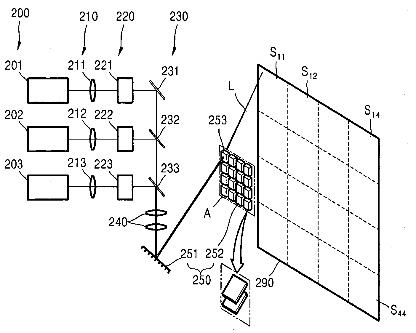
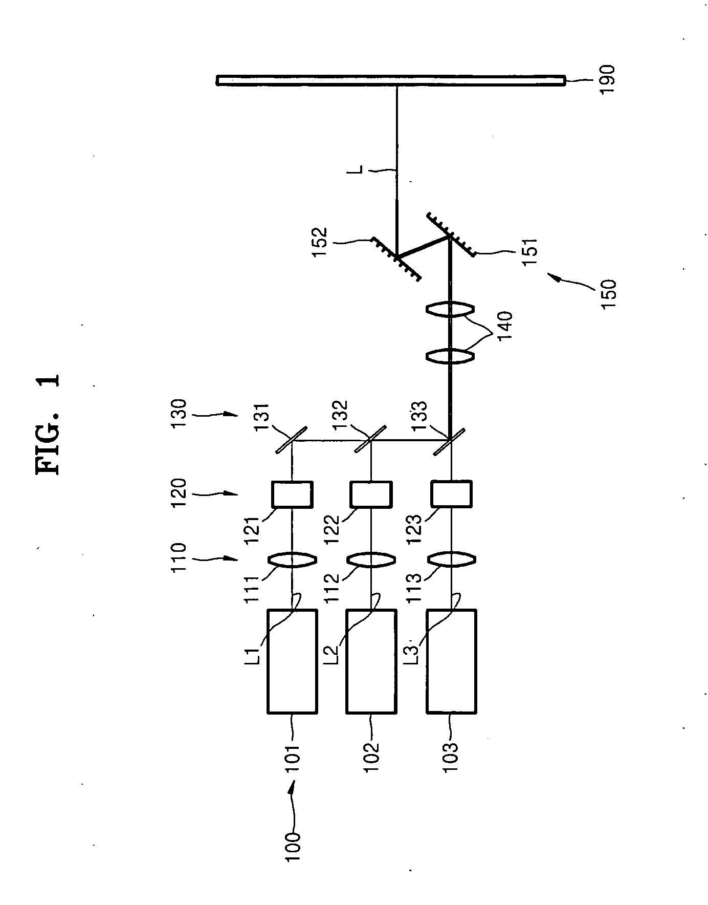
[0020]FIG. 1 is a schematic view of a laser display device according to an embodiment of the present invention. Referring to FIG. 1, the laser display device includes a light source 100 emitting a laser beam L, a light modulation unit 120 modulating the laser beam L according to an image signal, a light path converter 130 converting the light path to focus the modulated laser beams L from the light modulation unit 120, a scanning unit 150 scanning the modulated laser beams L, and an image unit 190 forming an image using excitation light generated by the scanned laser beams L.

[0021]The light source 100 is a laser emitting a laser beam L in the UV range. The light source 100 may be, for example, a nitride type semiconductor laser diode. The laser beam L emitted from the light source 100 generates photoluminescence in a phosphor (195 in FIG. 3...


PUM


Abstract

A laser display device is provided which includes: a light source emitting at least one laser beam; a light modulation unit for modulating the laser beam emitted from the light source according to an image signal; a scanning unit scanning the laser beam modulated in the light modulation unit in a main scanning direction and in a sub-scanning direction; and an image unit in which an image is formed having a phosphor layer in which excitation light is generated by a laser beam scanned by the scanning unit.

Description

CROSS-REFERENCE TO RELATED PATENT APPLICATION[0001]This application claims the benefit of Korean Patent Application No. 10-2006-0012603, filed on Feb. 9, 2006, in the Korean Intellectual Property Office, the disclosure of which is incorporated herein in its entirety by reference.BACKGROUND OF THE DISCLOSURE[0002]1. Field of the Disclosure[0003]The present disclosure relates to a laser display device, and more particularly, to a laser display device using light of a phosphor layer excited by a laser beam.[0004]2. Description of the Related Art[0005]A display device displays an image represented by an electric signal. An example of a conventional display device is a cathode ray tube (CRT).[0006]A CRT uses the luminescence of phosphor materials excited by electron beams. This principle is called cathode luminescence by electron beams. When using a cathode ray, it is difficult to reduce the thickness of the CRT or provide a large screen due to limitations in the structure of the vacuum ...

Claims


Application Information

Patent Timeline
Patent Type & Authority Applications(United States)
IPC IPC(8): H01S3/10H01S3/00
CPCH04N9/3129B26B13/20
Inventor SON, JOONG-KONLEE, JEONG-WOOKPAEK, HO-SUNLEE, SUNG-NAMSAKONG, TAN
Owner SAMSUNG ELECTRONICS CO LTD
Why Eureka
Try Eureka