Air treatment device with controlled pore size substrate

a treatment device and air technology, applied in the direction of biocide, plant/algae/fungi/lichens ingredients, drug compositions, etc., can solve the problems of increasing the cost of production, increasing the difficulty of controlling the dispensing, and often resting on the substrate, etc., to achieve the effect of extremely efficient heat use and low cos

Active Publication Date: 2007-08-09
SC JOHNSON & SON INC
View PDF11 Cites 9 Cited by
  • Summary
  • Abstract
  • Description
  • Claims
  • Application Information

AI Technical Summary

Benefits of technology

[0021] It should be appreciated that the substrates of the present invention are inexpensive to produce, use heat extremely efficiently, and are capable of multiple initiation bursts. The foregoing and other advantages of the present invention will be apparent from the following description. In the description that follows reference is made to the accompanying drawings which form a part thereof, and in which there is shown by way of illustration, and not limitation, expected preferred embodiments of the invention. Such embodiments do not necessarily represent the full scope of the invention, and reference should therefore be made to the claims herein for interpreting the scope of the invention.

Problems solved by technology

One problem with such devices is that the substrate usually rests against or near a heater.
This can create some inefficiencies.
For example, the portion of the substrate adjacent the heater can act as an insulator for the portion of the substrate which is releasing the active, making control of the dispensing more difficult.
Another problem with such devices is that it may take a while after usage begins to adequately treat the air in a defined environment adjacent the device.
It is undesirable for them to have to wait a long period before feeling secure about insect protection in the room.
While these patents therefore addressed the need for quickly treating a room at the beginning of operation, they did not address a way to have the same device provide such a burst on multiple days.
However, these wicks were not provided with a means of creating a quick start-up burst, much less a rechargeable start-up burst.

Method used


Image

  • Air treatment device with controlled pore size substrate
  • Air treatment device with controlled pore size substrate
  • Air treatment device with controlled pore size substrate

Examples


Embodiment Construction

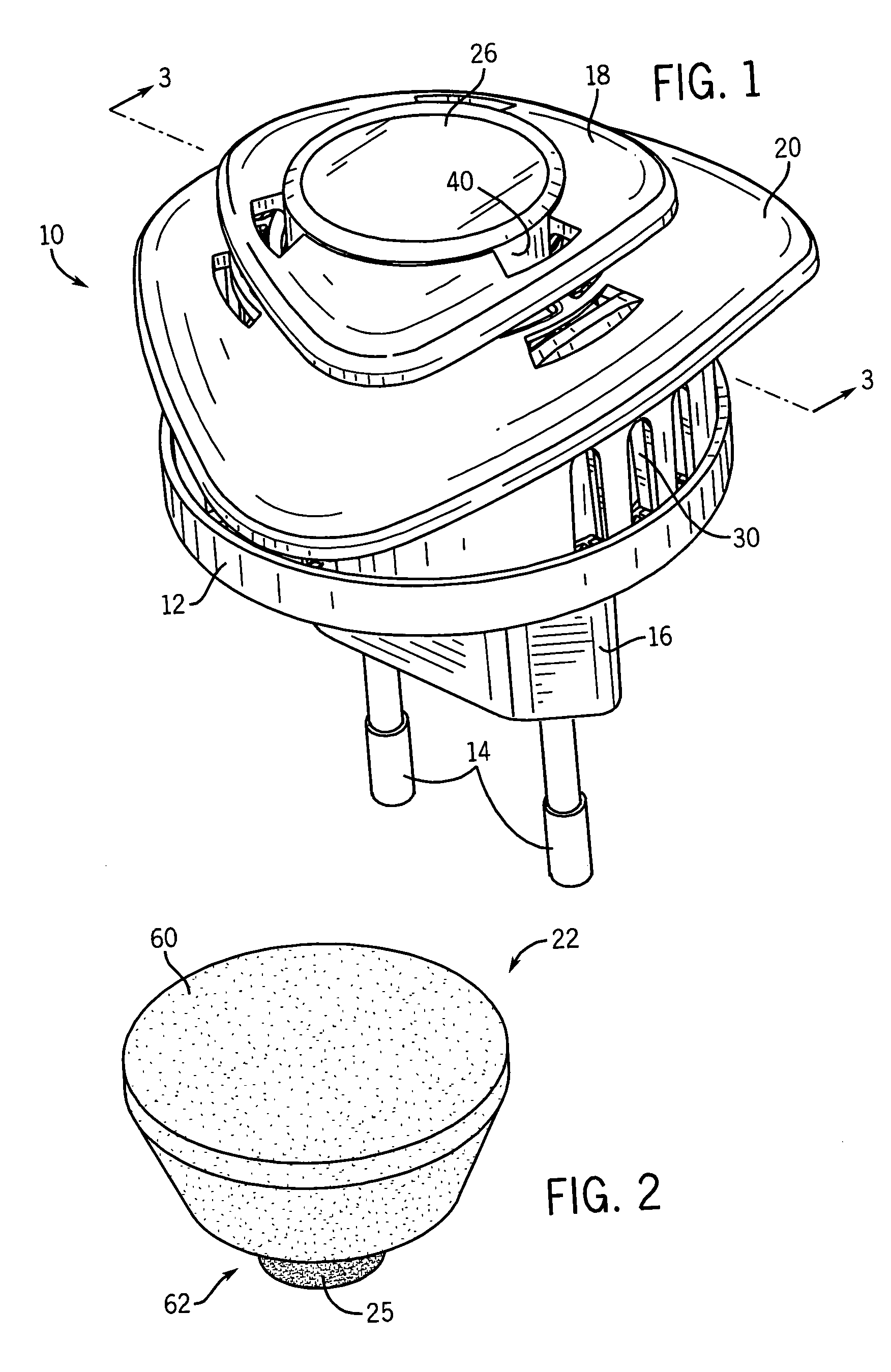
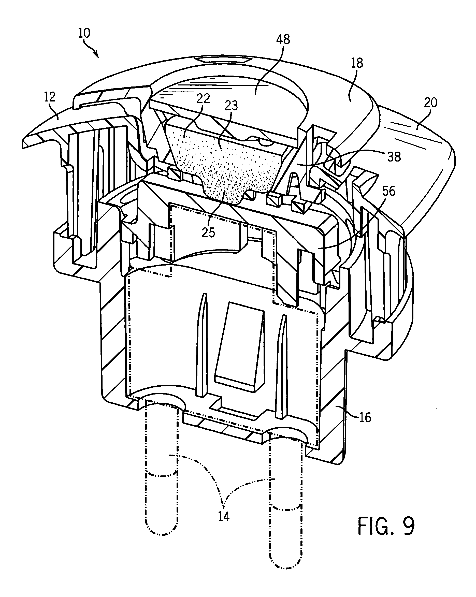
[0031] Referring first to FIG. 1, air treatment device 10 has a housing 12 with electrical prongs 14 at a rear end 16 and a removable cartridge unit 18 at an opposing forward end 20.

[0032] The cartridge unit 18 preferably has a substrate 22 mounted to project through its rearward end and a separately installable indicator unit 26 mounted to project out from its forward end. There is a substantially circular cavity 38 (see FIG. 3) in the rearward center of the unit 18 which tapers rearwardly to hold the substrate 22.

[0033] The indicator unit 26 is removable from the cartridge unit 18. The indicator unit 26 preferably houses a separate indicator chemical, which may indicate to a user the amount of air treatment chemical remaining in the substrate 22. A removable indicator unit 26 allows the indicator unit 26 and / or the substrate 22 to be separately replaced. However, the indicator chemical may be directly housed in a well of the cartridge unit 18.

[0034] The device 10 is most prefer...


PUM

PropertyMeasurementUnit
diameteraaaaaaaaaa
diameteraaaaaaaaaa
sizeaaaaaaaaaa

Abstract

Disclosed are substrates suited for dispensing air treatment chemicals upon being heated. Granular particles, preferably sand with a phenolic binder, are adhered together to form a substrate body having a network of pores. A volatile air treatment chemical is disposed in the pores. The particle size and pores are such that the smaller particles of the substrate are grouped at one end, preferably an end adjacent to a projecting nose. This structure tends to wick the volatile air treatment chemical towards the nose, and heating that area can lead to efficient, and rechargeable, dispensing. Methods for using such substrates, and methods for forming such substrates, are disclosed.

Description

CROSS-REFERENCE TO RELATED APPLICATIONS [0001] Not applicable. STATEMENT REGARDING FEDERALLY SPONSORED RESEARCH / DEVELOPMENT [0002] Not applicable BACKGROUND OF THE INVENTION [0003] The present invention relates to devices that dispense a volatile air treatment chemical by heating a substrate that is impregnated with, or coated with, the chemical. More particularly it relates to methods for constructing the substrate to create an array of pore size distribution therein, substrates produced thereby, and such substrates further formed with a rechargeable start-up projection. [0004] Substrates (particularly porous substrates) have previously been used as carriers for air treatment chemicals such as insect control agents (insecticides, insect repellents, insect growth regulators, attractants, synergists, etc.), fragrances and deodorizers. See e.g. U.S. Pat. No. 6,551,560. The disclosure of this patent, and of all other patents referred to herein are incorporated by reference as if fully ...

Claims


Application Information

Patent Timeline
Patent Type & Authority Applications(United States)
IPC IPC(8): A01N25/00
CPCA01M1/2077A61L9/037Y10S424/08Y10S424/10Y10S514/919Y10T428/249953A61L9/012A61L9/01A61L9/02
Inventor VARANASI, PADMA PRABODHADAIR, JOEL E.
Owner SC JOHNSON & SON INC
Why Eureka
Try Eureka