Printed circuit board

Inactive Publication Date: 2007-08-09
CANON KK
View PDF8 Cites 20 Cited by
  • Summary
  • Abstract
  • Description
  • Claims
  • Application Information

AI Technical Summary

Benefits of technology

[0019]It is an object of the present invention to provide a highly reliable printed circuit board which is cap

Problems solved by technology

However, the above-described junction structure of the conventi

Method used


Image

  • Printed circuit board
  • Printed circuit board
  • Printed circuit board

Examples


Embodiment Construction

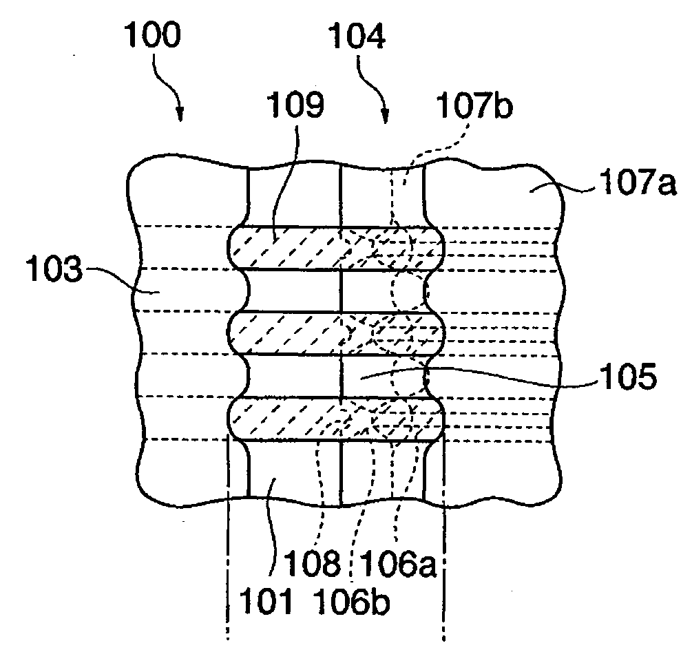
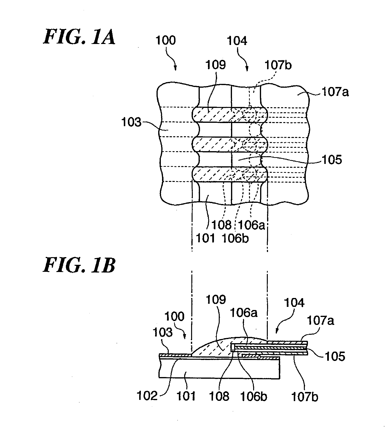
[0036]The present invention will now be described in detail below with reference to the drawings showing a preferred embodiment thereof.

[0037]A junction structure of a printed circuit board according to the present embodiment is produced by aligning a flexible printed circuit board and a rigid printed circuit board having a structure characterizing the present embodiment, one upon the other, and then electrically connecting the two by soldering. First, a description will be given of an unsoldered state of the junction structure of the printed circuit board according to the present embodiment, and then of a method of joining the rigid printed circuit board and the flexible printed circuit board.

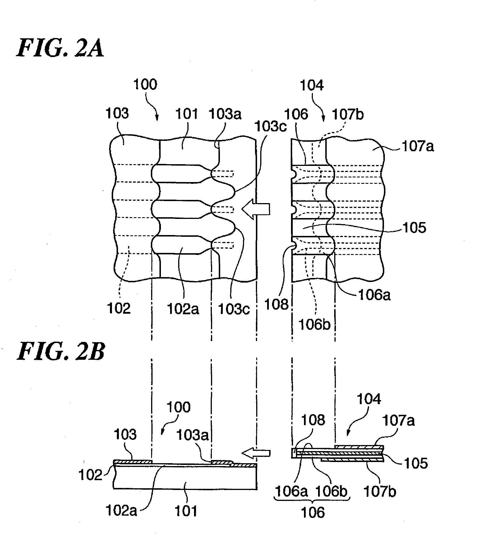
[0038]FIGS. 1A and 1B are views of the junction structure of the printed circuit board according to the present embodiment. FIG. 1A is a top view of the junction structure, and FIG. 1B is a cross-sectional view of the same. FIGS. 2A and 2B are views of the printed circuit board in FIGS. 1A and...


PUM


Abstract

A highly reliable printed circuit board which is capable of preventing a short circuit between traces from being caused by a solder bridge formed by excess solder. The printed circuit board has a solder resist covering copper foil traces formed on a substrate and the substrate, for insulation. The solder resist is formed such that exposed portions of the substrate between adjacent ones of the conductive traces each have a shape protruding in a direction of where the other printed circuit board is connected, with respect to exposed portions of the adjacent ones of the conductive traces, in a boundary between the connection part and a portion on which an insulating layer is formed.

Description

BACKGROUND OF THE INVENTION[0001]1. Field of the Invention[0002]The present invention relates to a printed circuit board which electrically connects exposed conductor patterns formed on a printed circuit board to each other using a conductive joining material, such as solder.[0003]2. Description of the Related Art[0004]Conventionally, there has been proposed a junction structure that electrically connects exposed conductor patterns formed on a printed circuit board to each other by soldering or the like (see e.g. Japanese Laid-Open Patent Publications (Kokai) No. S61-224494 and No. H10-173335). In the following, the junction structure of a conventional general printed circuit board will be described with reference to FIGS. 4A and 4B.[0005]FIGS. 4A and 4B are views showing an example of a first junction structure of the conventional printed circuit board. FIG. 4A is a top view of the first junction structure, and FIG. 4B is a cross-sectional view of the same.[0006]In this junction st...

Claims


Application Information

Patent Timeline
IPC IPC(8): H05K1/00
CPCH05K3/3452H05K3/363H05K2201/0989H05K2201/09727H05K2201/09181
Inventor ISHIKAWA, KOJI
Owner CANON KK
Why Eureka
Try Eureka