Method and system for location of objects within a specified geographic area

a technology of geographic area and method, applied in the direction of wireless communication, electrical equipment, selection arrangements, etc., can solve the problems of reducing wasting time and human resources, and based systems that create significant problems for parking lot operators, so as to reduce the effect of multipath interference and enhance the accuracy of location calculation

Inactive Publication Date: 2007-08-09
LOTTRAK
View PDF12 Cites 176 Cited by
  • Summary
  • Abstract
  • Description
  • Claims
  • Application Information

AI Technical Summary

Benefits of technology

[0008] In a further embodiment, one or more Vmotes and optionally one or more beacons forming a wireless mesh network utilize multiple ranging signals transmitted at various frequencies, various power levels, and/or modulated with different modulation parameters (e.g., amplitude, frequency, phase, etc.) to reduce the effects of multipath interference. In one embodiment, a stationary Vmote or a beacon transmits a plurality of reference signals utilizing various predetermined frequencies, power levels and/or modulation parameters. These multiple transmissions reduce multipath effects which are

Problems solved by technology

These manually based systems create significant problems for parking lot operators since vehicles are often moved around to different parking spaces as well as being removed or introduced to the parking lot.
In facilities utilizing these manual systems, it is often difficult and time-consuming to locate a particular vehicle of interest which results in wasted time and human resources.
Existing wireless location techniques are relatively inaccurate and not well-suited for determining the precise location of an object.
Additionally, traditional WiFi communication protocols are optimized for data communication, not providing accurate location se

Method used


Image

  • Method and system for location of objects within a specified geographic area
  • Method and system for location of objects within a specified geographic area
  • Method and system for location of objects within a specified geographic area

Examples


Embodiment Construction

[0020] In the following description of exemplary embodiments, reference is made to the accompanying drawings which form a part hereof, and in which it is shown by way of illustration specific embodiments in which the invention may be practiced. It is to be understood that other embodiments may be utilized and structural changes may be made without departing from the scope of the present invention.

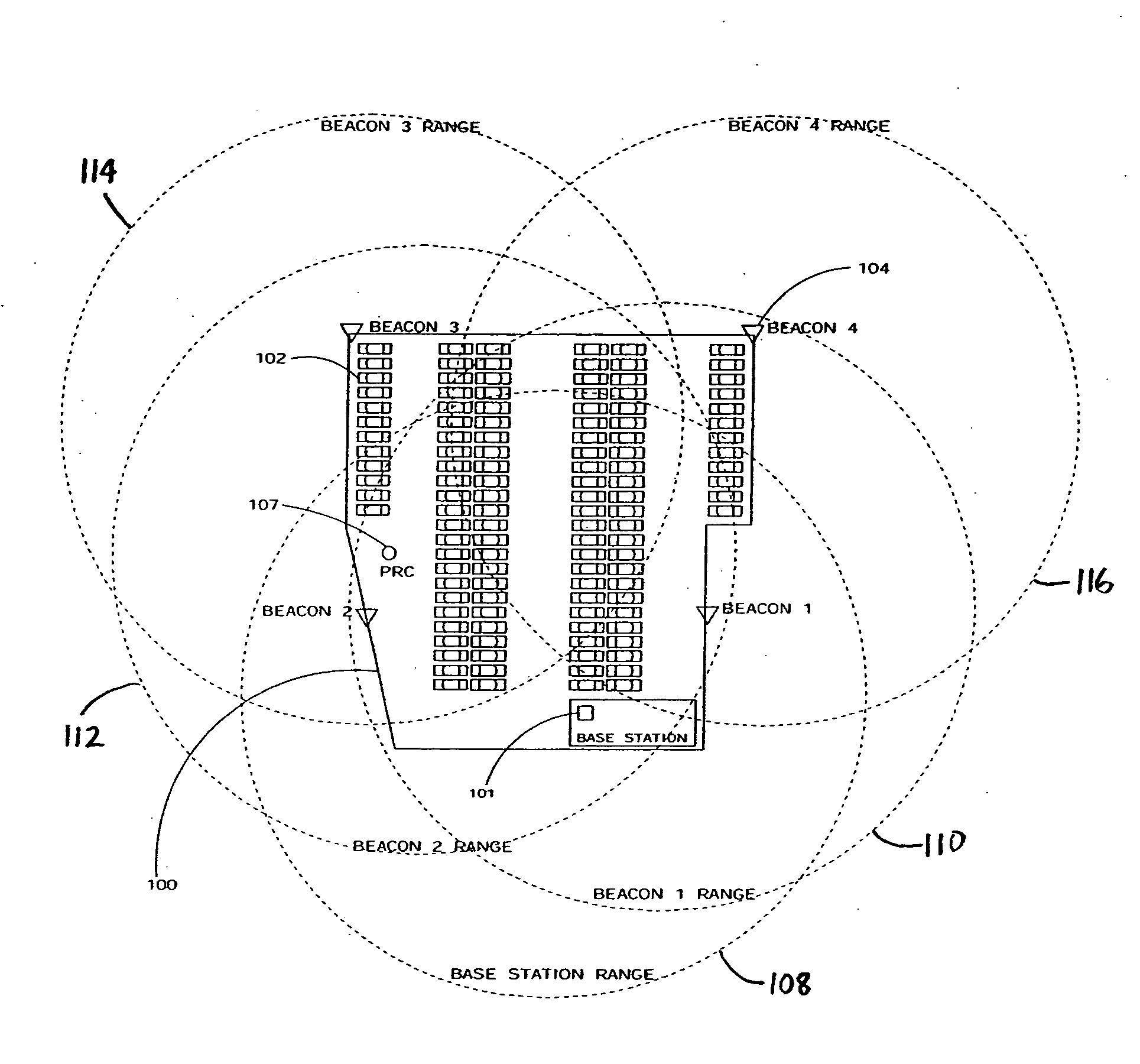
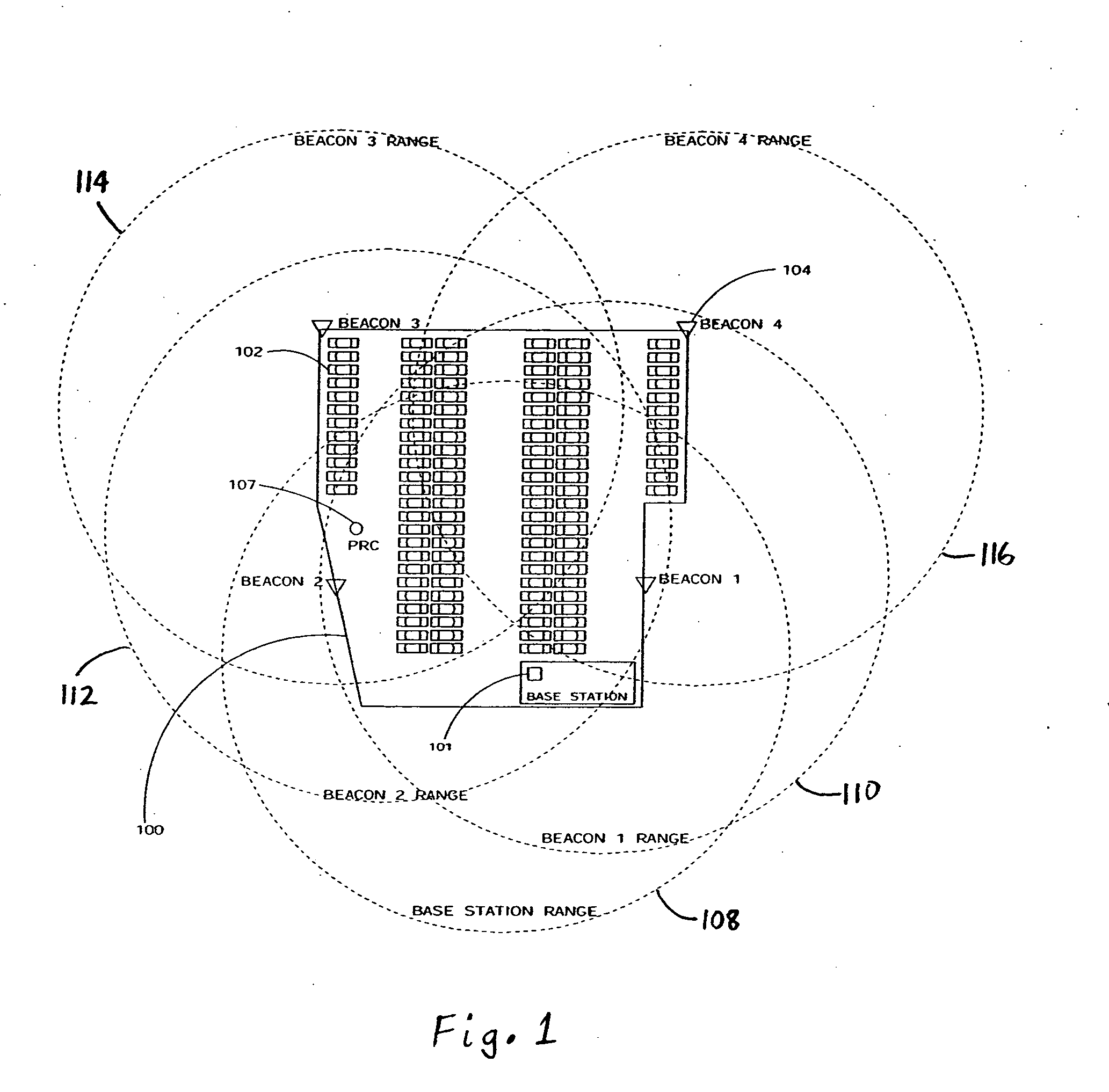
[0021]FIG. 1 illustrates a typical parking lot area 100 of arbitrary shape and dimensions wherein a mesh communication network is established to rapidly and accurately identify the location of vehicles, in accordance with one embodiment of the invention. The mesh network includes a base station 101 at an arbitrary location within the lot area 100, a plurality of vehicles 102 each equipped with a portable transceiver device (not shown) attached to or contained within each vehicle 102, and a plurality of stationary communication nodes or beacons 104 positioned at relative locations across th...


PUM


Abstract

A method and system for determining the location of objects within a geographic area is disclosed. In one embodiment, the system includes a plurality of portable transceiver devices each coupled to a respective object located within the geographic area; a plurality of stationary transceiver devices fixed at predetermined locations within the geographic area, wherein the plurality of stationary transceiver devices are each configured to determine received signal strength (RSSI) values of signals transmitted by the plurality of portable transceiver devices; and a base station, comprising a base station transceiver device and a computer coupled to the base station transceiver device, wherein the base station is configured to receive RSSI values from at least one of the plurality of stationary transceiver devices and calculate a location of at least one portable transceiver device based on the received RSSI values.

Description

RELATED APPLICATIONS [0001] This application claims priority under 35 U.S.C. § 119(e) to U.S. Provisional Application Ser. No. 60 / 759,774, entitled “Process Methods and Apparatus for Autolocation of Specific Vehicles of Interest Within a Parking Area,” filed on Jan. 17, 2006, the entirety of which is incorporated by reference herein.FIELD OF THE INVENTION [0002] The invention relates generally to locating objects using radio frequency (RF) signals and more particularly, to a method and system for utilizing received signal strength indications (RSSI) to calculate and identify the location of objects within a specified geographic area. BACKGROUND OF THE INVENTION [0003] Current methods used by operators of parking areas such as car lots, service stations and fleet operations involve periodic manual inventory procedures and tracking systems based on key pegs, bar coded stock stickers and numbered parking places. These manually based systems create significant problems for parking lot o...

Claims


Application Information

Patent Timeline
IPC IPC(8): H04Q7/20H04W64/00
CPCH04W64/00
Inventor JOHNSON, DAVID W.LA ROVERE, THOMAS A.WEAVER, LARRYBIVANS, BRUCE W.
Owner LOTTRAK
Why Eureka
Try Eureka