Robotic surgical system

a robotic surgery and robotic technology, applied in the field of robotic surgery, can solve the problems of high degree of fatigue in the physician, substantial amount of time and skill, etc., and achieve the effects of reducing radiation exposure, reducing time required, and minimizing the need for fluoroscopy

Active Publication Date: 2007-08-09
ST JUDE MEDICAL ATRIAL FIBRILLATION DIV
View PDF102 Cites 124 Cited by
  • Summary
  • Abstract
  • Description
  • Claims
  • Application Information

AI Technical Summary

Benefits of technology

[0022] An advantage of the present invention is a reduced exposure to radiation for both the patient and the physician, since the present invention reduces the time required to navigate the catheter to a target location and minimizes the need for fluoroscopy to locate the catheter within the patient.
[0023] Another advantage of the present invention is the ability to easily switch between automated robotic control and manual control of the catheter.
[0024] Still another advantage of the present invention is the ability to remotely interact with the robotic surgical system controlling the catheter.
[0025] The foregoing and other aspects, features, details, utilities, and advantages of the present invention will be apparent from reading the following description and claims, and from reviewing the accompanying drawings.

Problems solved by technology

Navigating a catheter reliably through the patient's body to a precise location, however, is an extremely tedious process requiring a substantial amount of time and skill and potentially causing a high degree of fatigue in the physician, especially where actuation forces are transmitted over large distances.

Method used


Image

  • Robotic surgical system
  • Robotic surgical system
  • Robotic surgical system

Examples


Embodiment Construction

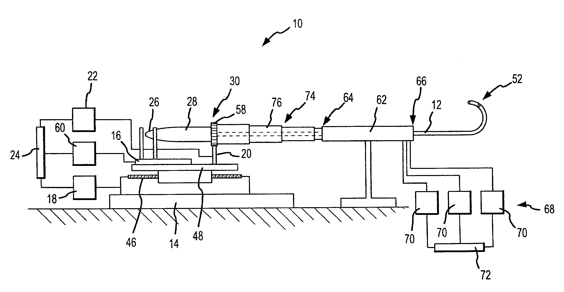
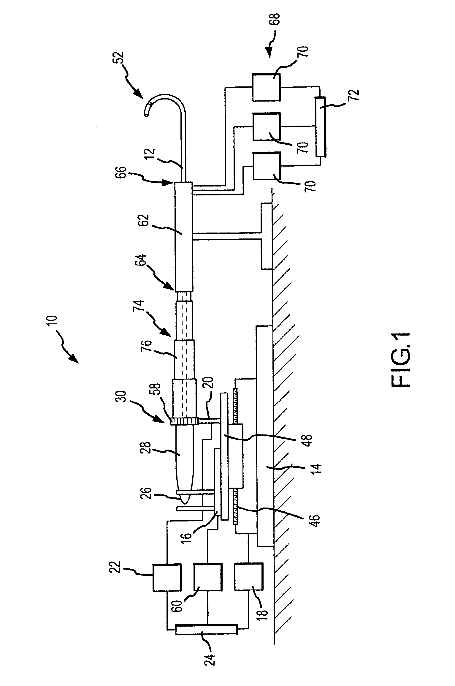
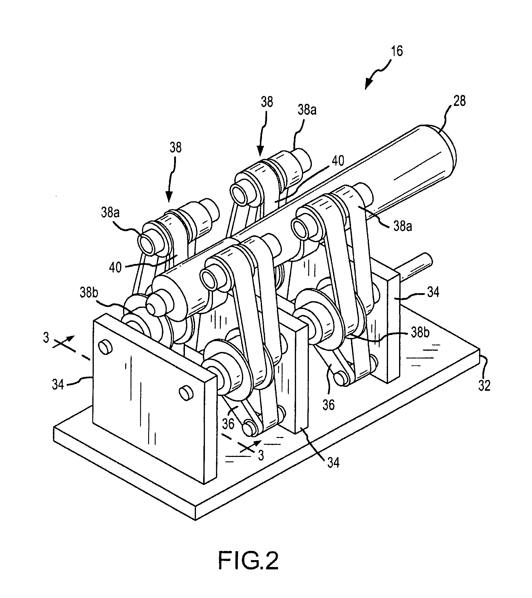
[0035]FIG. 1 schematically illustrates an embodiment of a robotic surgical system 10 for robotic manipulation and control of a medical device 12. Medical device 12 is preferably a catheter, which may be any type of catheter, including, by way of example only and without limitation, an ablation catheter, a guide wire catheter, an introducer catheter, a probe, or a stylet. It should be understood, however, that any other therapeutic, diagnostic, or assistive medical device may be controlled by robotic surgical system 10 without departing from the scope of the present invention. Such other devices include, but are not limited to, syringes, electrophoresis devices, iontophoresis devices, transdermal pharmaceutical delivery devices, myoblast delivery devices, stem cell delivery devices, ablation devices, stents, and pacemaker leads, which may be carried on or delivered by a catheter. It should further be understood that robotic surgical system 10 may be used to manipulate and control mor...


PUM


Abstract

A robotic surgical system includes a track, a catheter holding device including a catheter receiving portion translatably associated with the track, a translation servo mechanism to control translation of the catheter holding device relative to the track, a catheter deflection control mechanism, a deflection servo mechanism to control the catheter deflection control mechanism, and a controller to control at least one of the servo mechanisms. The catheter receiving portion is adapted for quick installation and removal of a catheter. The catheter receiving portion may be rotatable, with a rotation servo mechanism to control the rotatable catheter receiving portion. The controller controls at least one of the deflection and rotation servo mechanisms to maintain a substantially constant catheter deflection as the catheter rotates. An introducer, which may be steerable, and an expandable, collapsible sterile tube may also be provided.

Description

CROSS-REFERENCE TO RELATED APPLICATIONS [0001] This application claims the benefit of U.S. provisional application No. 60 / 851,042, filed 12 Oct. 2006, which is hereby expressly incorporated by reference as though fully set forth herein. [0002] This application is a continuation-in-part of U.S. application Ser. No. 11 / 139,908, filed 27 May 2005 (the '908 application), now pending, which claims the benefit of U.S. provisional application No. 60 / 575,741, filed 28 May 2004 (the '741 application). The '908 and '741 applications are hereby expressly incorporated by reference as though fully set forth herein.BACKGROUND OF THE INVENTION [0003] a. Field of the Invention [0004] The instant invention relates to robotically controlled medical devices. In particular, the instant invention relates to a robotic surgical system for navigating a medical device through a patient's body for diagnostic and therapeutic purposes. [0005] b. Background Art [0006] Catheters are used for an ever growing numb...

Claims


Application Information

Patent Timeline
Patent Type & Authority Applications(United States)
IPC IPC(8): A61B18/18
CPCA61B5/6885A61B19/22A61B19/2203A61B19/5244A61B2017/00026A61M25/0105A61B2019/2242A61B2019/2276A61B2019/464A61B2019/5251A61B2019/528A61B2019/2211A61B34/20A61B34/30A61B34/70A61B34/71A61B2034/2051A61B2034/301A61B2034/742A61B2090/064A61B2090/3784
Inventor HAUCK, JOHN A.SCHWEITZER, JEFFREY A.TEGG, TROY T.ESSINGTON, JAMES D.JOHNSON, MARK T.BELHE, KEDAR RAVINDRA
Owner ST JUDE MEDICAL ATRIAL FIBRILLATION DIV
Why Eureka
Try Eureka