Manufacturing apparatus

a technology of manufacturing apparatus and el material, which is applied in the direction of vacuum evaporation coating, chemical vapor deposition coating, coating, etc., can solve the problems of difficult control of deposition speed, difficult to heat or cool substances easily under vacuum, and take time for cooling el material, etc., to achieve excellent uniformity or throughput, promote the efficiency of utilizing el material, and reduce manufacturing costs

Inactive Publication Date: 2007-08-16
SEMICON ENERGY LAB CO LTD
View PDF45 Cites 36 Cited by
  • Summary
  • Abstract
  • Description
  • Claims
  • Application Information

AI Technical Summary

Benefits of technology

[0012] The present invention provides a vapor deposition apparatus as one of the manufacturing apparatus that promotes an efficiency of utilizing an EL material to reduce manufacturing costs and is excellent in uniformity or throughput of forming an EL layer and a vapor deposition method. Further, the present invention provides a light emitting device fabricated by the vapor deposition apparatus and the vapor deposition method according to the present invention and a manufacturing method of the light emitting device.
[0033] According to the above-described structure, a throughput is enhanced since a substrate can be deposited while delivered.

Problems solved by technology

Also, it takes time for cooling the EL material.
In particular, substances are not heated nor cooled easily under vacuum.
Further, when a large amount of EL material is divided into a plurality of crucibles, it becomes difficult to control the deposition speed of each crucible; therefore it becomes difficult to keep a film thickness even.
Moreover, even though a plurality of heaters and crucibles are provided, it is difficult to provide a plurality of identical evaporation sources due to small differences in quality and shape.

Method used


Image

  • Manufacturing apparatus
  • Manufacturing apparatus
  • Manufacturing apparatus

Examples


embodiment mode 1

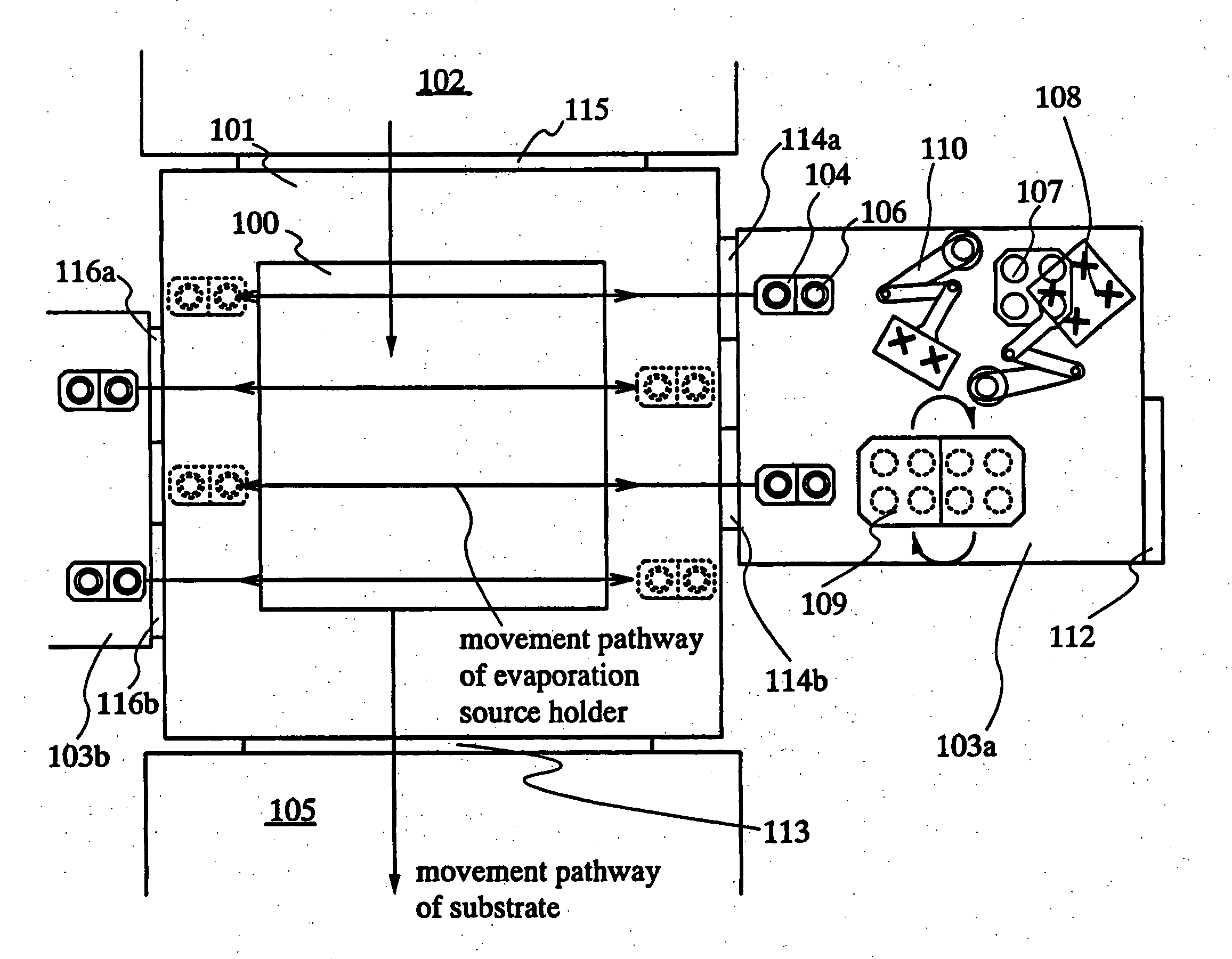
[0049]FIG. 1 shows a top plan view of a manufacturing apparatus of the invention.

[0050] In FIG. 1, reference numeral 100 is a substrate, 101 is a film formation chamber, 102 and 105 are delivery chambers, 103a and 103b are crucible setting chambers, 104 is an evaporation source holder, 106 is a crucible, 101 is a lid setting table, 108 is a lid delivery robot, 109 is a container setting turntable, 110 is a crucible delivery robot, 112 is a door, 113, 114a, 114b, 115, 116a, and 116b are shutters dividing each chamber.

[0051] The substrate 100 is delivered from the delivery chamber 102 into the film formation chamber 101. In the case of depositing selectively, an alignment of an evaporation mask and the substrate is performed prior to the deposition.

[0052] In the evaporation source holder 104, two crucibles in which EL materials are stored 106 are provided. Note that a sliding shutter (not shown) is provided for each crucible. FIG. 1 shows an example in which an evaporation source h...

embodiment mode 2

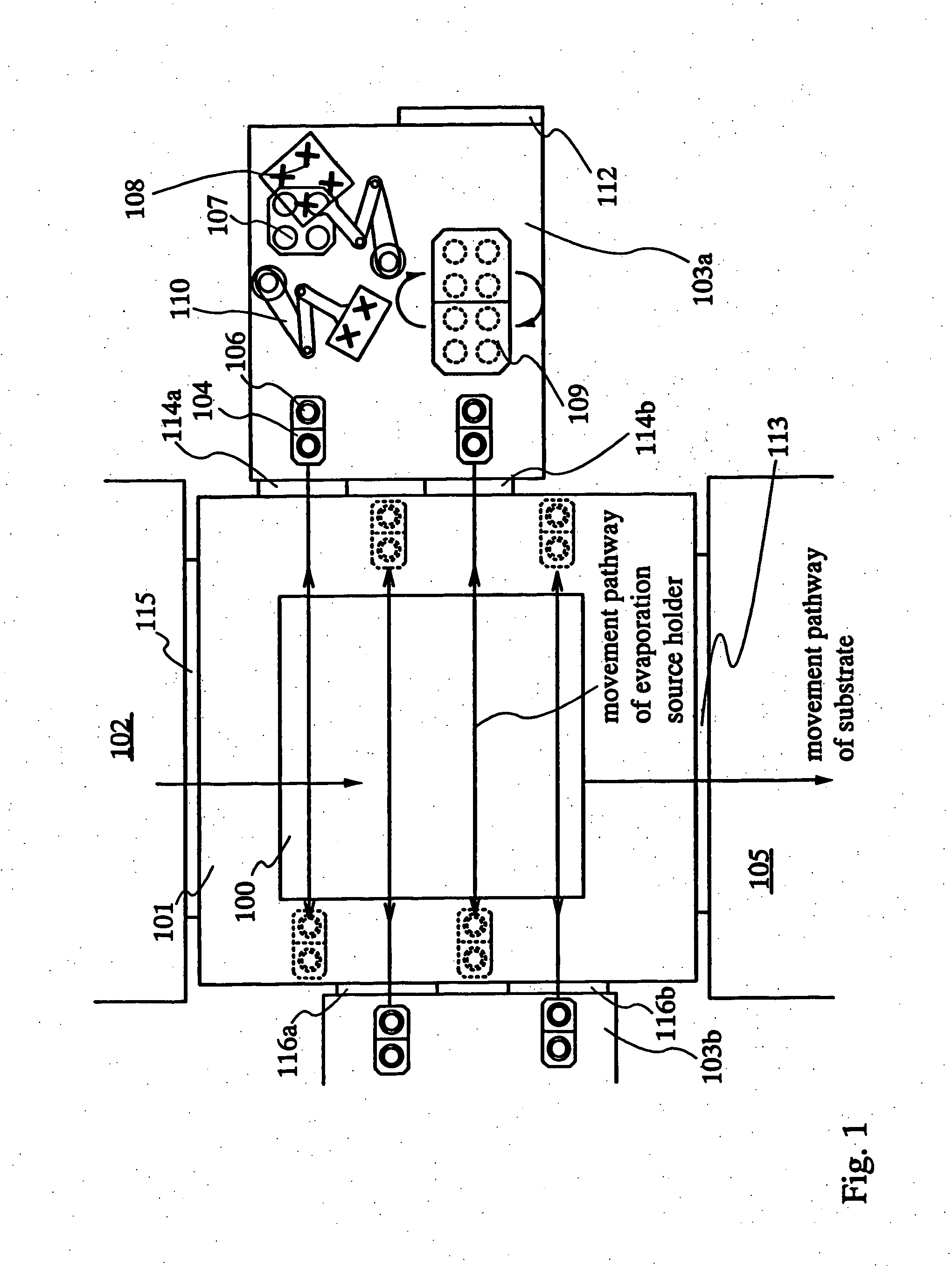
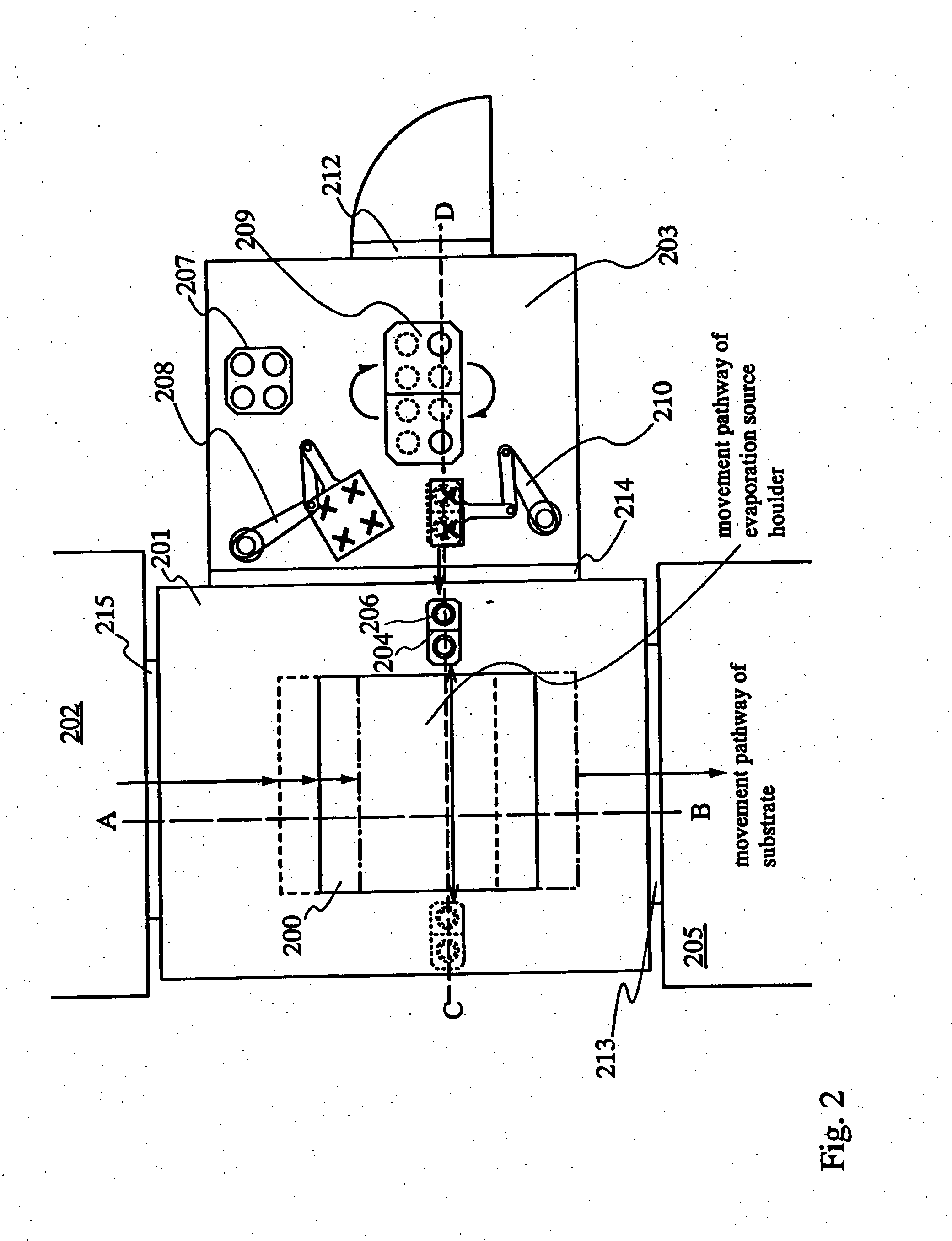
[0065]FIG. 2 shows another example of the manufacturing apparatus of the invention.

[0066] The manufacturing apparatus shown in FIG. 2 has one evaporation source holder and one crucible setting chamber in one film formation chamber.

[0067] In FIG. 2, reference numeral 200 is a substrate, 201 is a film formation chamber, 202 and 205 are delivery chambers, 203 is a crucible setting chamber, 204 is an evaporation source holder, 206 is a crucible, 207 is a lid setting table, 208 is a lid delivery robot, 209 is a container setting turntable, 210 is a crucible delivery robot, 212 is a door, 213, 214 and 215 are shutters for dividing each chamber.

[0068] A sectional view taken by cutting along a dotted line A-B in FIG. 2 is shown in FIG. 3A, and a sectional view taken by cutting along a dotted line C-D in FIG. 2 is shown in FIG. 3B. Here, a direction of the dotted line A-B is referred to as a Y direction of the substrate and a direction of the dotted line C-D is referred to as an X directi...

embodiment mode 3

[0088] FIGS. 5A-SE shows an example of co-deposition. Note that a vapor deposition apparatus shown in FIGS. 5A-5E are different from FIGS. 1 and 2.

[0089] While the evaporation source holders shown in FIGS. 1 and 2 are movable into the crucible setting chamber, the evaporation source holder shown in FIG. 5A moves only inside the film formation chamber in the vapor deposition system. The evaporation source holder shown in FIG. 5A moves shorter distance as compared to the ones shown in FIGS. 1 and 2, therefore the compactness of the vapor deposition apparatus can be realized.

[0090] In FIG. 5A, reference numeral 400 is a substrate, 401 is a film formation chamber, 402 and 405 are delivery chambers, 403a and 403b are crucible setting chambers, 404a to 404d are evaporation source holders, 406 is a crucible, 407 is a lid setting table, 408 is a lid delivery robot, 409 is a container setting turntable, 410 is a crucible delivery robot, 412 is a door, 413, 414, 415, and 416 are shutters fo...


PUM

PropertyMeasurementUnit
distanceaaaaaaaaaa
sizeaaaaaaaaaa
sizeaaaaaaaaaa

Abstract

The purpose of the invention is increasing the efficiency of utilizing an EL material and providing a deposition method and a vapor deposition apparatus which is one of the film formation systems which are excellent in throughput and uniformity in film thickness in forming an EL layer. According to the invention, evaporation is performed by moving or reciprocating an evaporation source holder in which a plurality of containers (crucible) each encapsulating an evaporation material are set only in an X direction while moving a substrate at regular intervals. Further, in the plurality of evaporation source holders, film thickness meters of adjacent evaporation sources are disposed alternately so as to sandwich the movement pathway of the substrate.

Description

BACKGROUND OF THE INVENTION [0001] 1. Field of the Invention [0002] The present invention relates to a manufacturing apparatus having a film formation system for depositing materials which can be deposited by vapor deposition (hereinafter, an evaporation material), a light emitting device which has an organic compound layer as a light emitting layer and for which the manufacturing apparatus is used, and a manufacturing method thereof. Specifically, the invention relates to a manufacturing apparatus and a film formation method (a vapor deposition method) for forming a film by vaporizing an evaporation material from a plurality of evaporation sources disposed to be opposite to a substrate. [0003] 2. Description of the Related Art [0004] In recent years, research related to a light emitting device having an EL element as a self-luminous light emitting element has been advanced. The light emitting device is referred to as an organic EL display or an organic light emitting diode. Since t...

Claims


Application Information

Patent Timeline
Patent Type & Authority Applications(United States)
IPC IPC(8): C23C16/00C23C14/12C23C14/24C23C14/56
CPCC23C14/12H01L51/56C23C14/56C23C14/246H10K71/00
Inventor SAKATA, JUNICHIROYAMAZAKI, SHUNPEI
Owner SEMICON ENERGY LAB CO LTD
Why Eureka
Try Eureka