Type of loop heat conducting device

a heat conducting device and loop technology, applied in the direction of indirect heat exchangers, lighting and heating apparatus, etc., can solve the problems of small scale production and high cost of known loop heat pipes, and achieve optimal heat dissipation performance, increase in capillary force, and increase in flow resistance

Active Publication Date: 2007-08-16
YEH CHIANG TECH CORP
View PDF7 Cites 45 Cited by
  • Summary
  • Abstract
  • Description
  • Claims
  • Application Information

AI Technical Summary

Benefits of technology

[0006] In the heat conducting device of the present invention, the wick network core is contained only inside the evaporator, wherein a vapor chamber and a compensation chamber are formed inside the evaporator, and makes use of a circulation principle based on the separation of gas and liquid, and a smooth pipe is used as the transmission path. In comparison with the traditional wick pipe core that makes up almost the entire pipe route, the flow of the liquid working medium through the inside of the wick network core merely takes up a small portion of the entire route. This enables the capillary force to be increased, and also avoids an increase in the flow resistance of the liquid working medium inside the wick network core, thereby solving the issues of anti-gravitational operations and the flow resistance from long-distance heat transmission. The biggest difference from the traditional heat pipes is that the loop heat conducting device in the present invention is based on the design of separation of liquid and gas passages, such tha...

Problems solved by technology

The development of the performance of traditional heat-conducting pipes has already reached a limit, and the commonly-known loop...

Method used


Image

  • Type of loop heat conducting device
  • Type of loop heat conducting device
  • Type of loop heat conducting device

Examples


Embodiment Construction

[0020] The embodiments of the present invention will be described in detail below, but it should be understood that these embodiments are merely the relatively preferred embodiments of the present invention and do not limit the scope of the present invention. The best understanding can be obtained by reading the explanation of the embodiments set out below in conjunction with the diagrams.

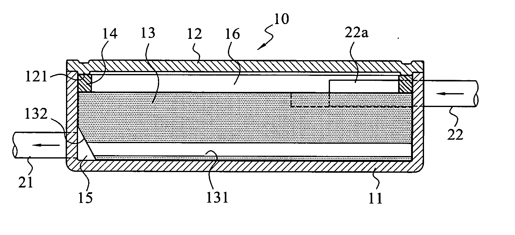
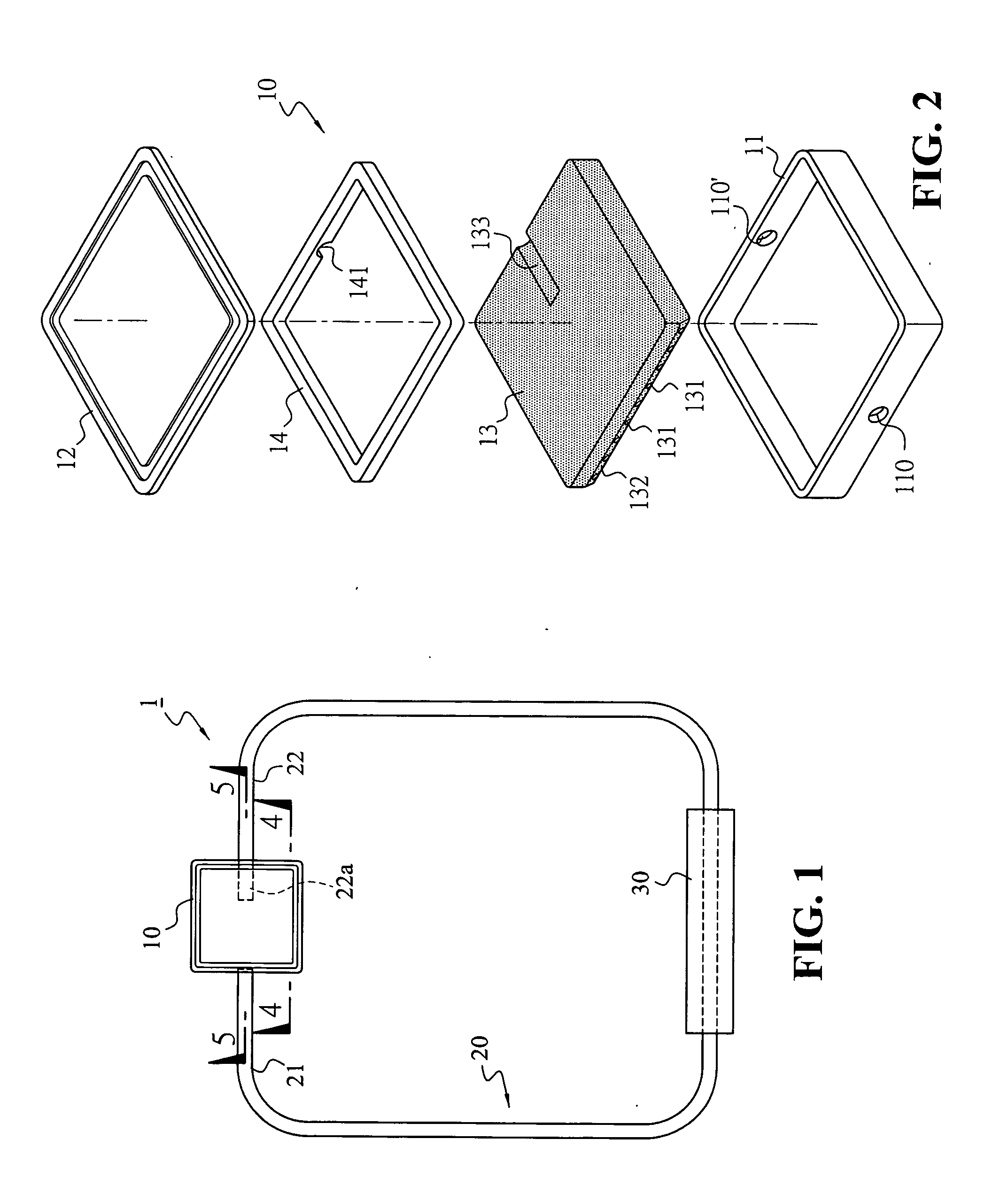
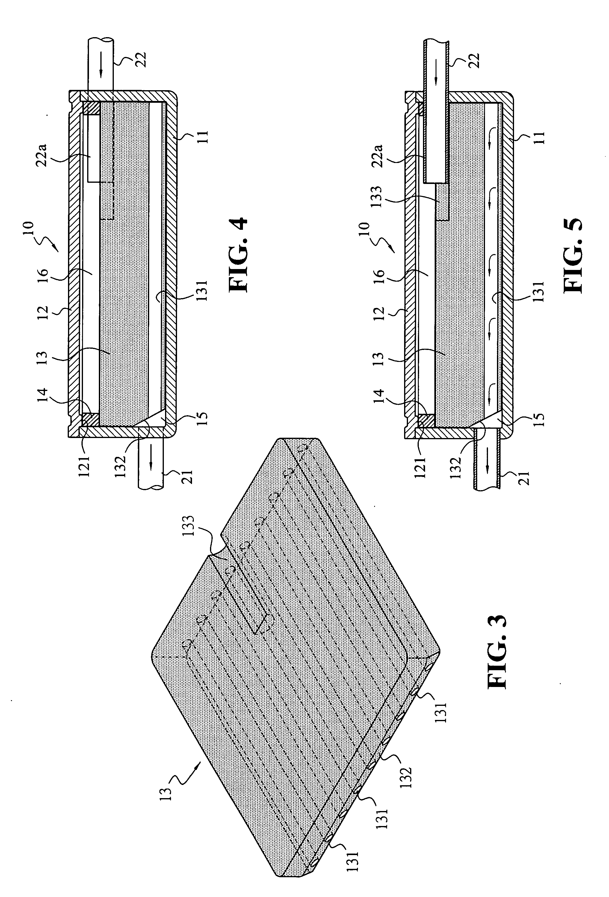
[0021] First, FIGS. 1 to 5 show an embodiment of the loop heat conducting device in the present invention (1). As shown in FIG. 1, the device primarily comprises an evaporator (10) and a condenser (30) which are connected together by means of a loop pipe (20), in order to form a cyclic loop for a liquid working medium. FIG. 2 shows a perspective view of the disassembled state in an evaporator (10) in the present invention and FIG. 3 shows an enlarged perspective view of the first type of wick network core (13) in the present invention. FIGS. 4 and 5 shows the cross-sectional diagrams for the appli...


PUM


Abstract

This invention relates to a type of loop heat conducting device, comprising an evaporator and a condenser which are connected together by means of a loop pipe, in order to form a cyclic loop for a liquid working medium, wherein the evaporator has a wick network core, and multiple tunnels are formed on the wick network core, and one end of the tunnels converges at a vapor chamber and is connected to a loop pipe to form a gaseous working medium outlet, and the terminal end of the pipe extends into and comes into contact with the internal part of the wick network core, and a compensation chamber for liquid working medium is formed on the upper section of the wick network core. Consequently, the cyclic loop that separates the gas and liquid enables the optimal heat dissipation capacity, and also has a structure that is simplified, thereby allowing for easy mass production.

Description

TECHNICAL FIELD [0001] This invention relates to a type of heat conducting device, particularly a type of loop heat conducting device, wherein an evaporator and a condenser are connected together by means of a loop pipe in order to form a cyclic loop for a liquid working medium, and there is a vapor chamber and a compensation chamber that are installed in the evaporator to separate the liquid and gas, thereby achieving an optimal heat dissipation capacity. BACKGROUND OF THE INVENTION [0002] Following advances in technology, the development of electronic products has been growing rapidly. With a trend that is moving towards lighter, thinner, shorter, smaller and finer products, and increasingly high requirements for the product functions, the corresponding power that is used also becomes increasingly high. With the requirements for smaller size and more power, the concentration of heat generation over the surface of the electronic components will also increase rapidly, and the relate...

Claims


Application Information

Patent Timeline
IPC IPC(8): F28D15/04
CPCF28D15/046F28D15/043F28D15/0266
Inventor CHIN, CHI-TEWANG, CHIH-SHENGTU, TANG-HUNG
Owner YEH CHIANG TECH CORP
Why Eureka
Try Eureka