Embodiment 1
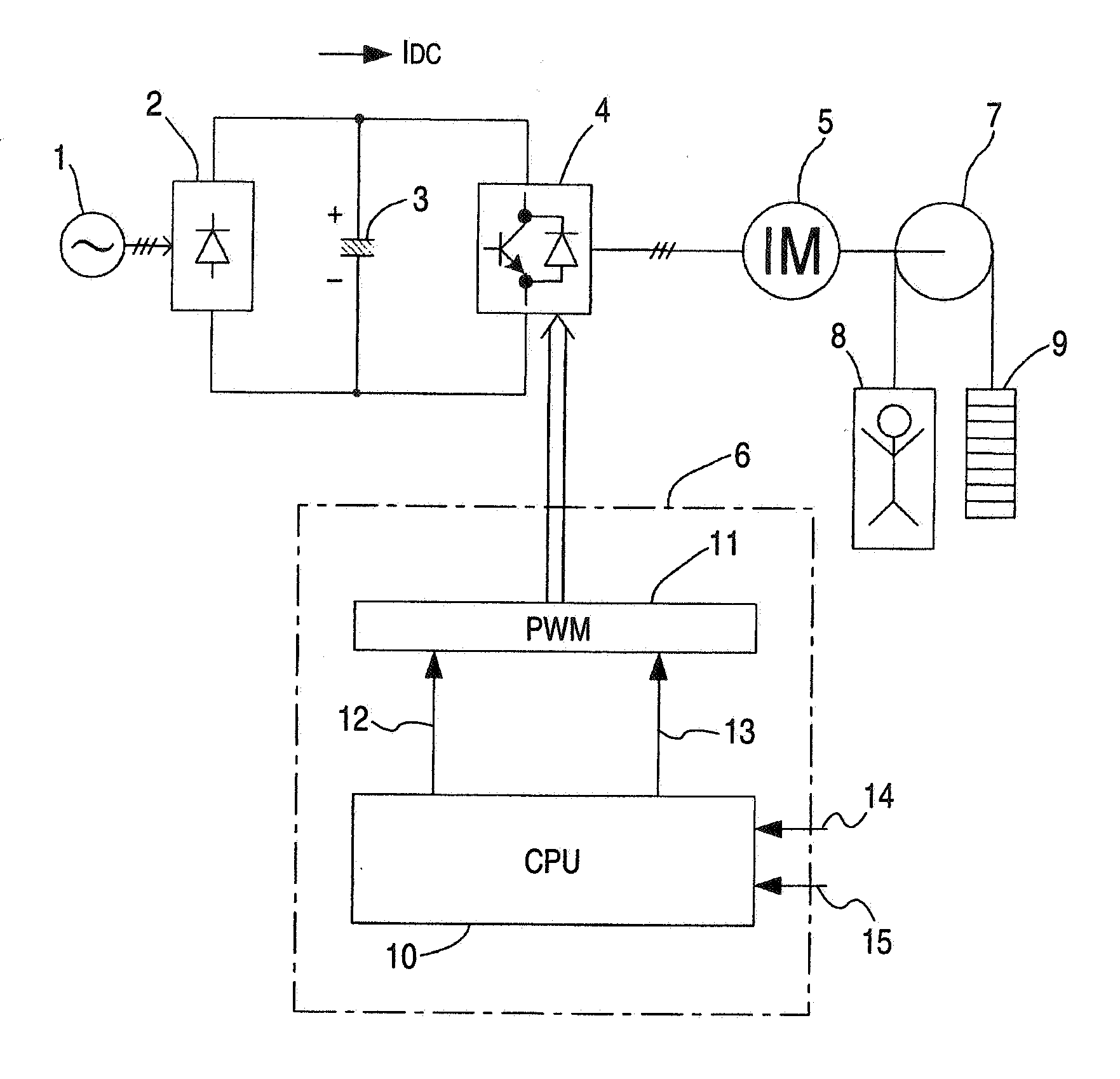
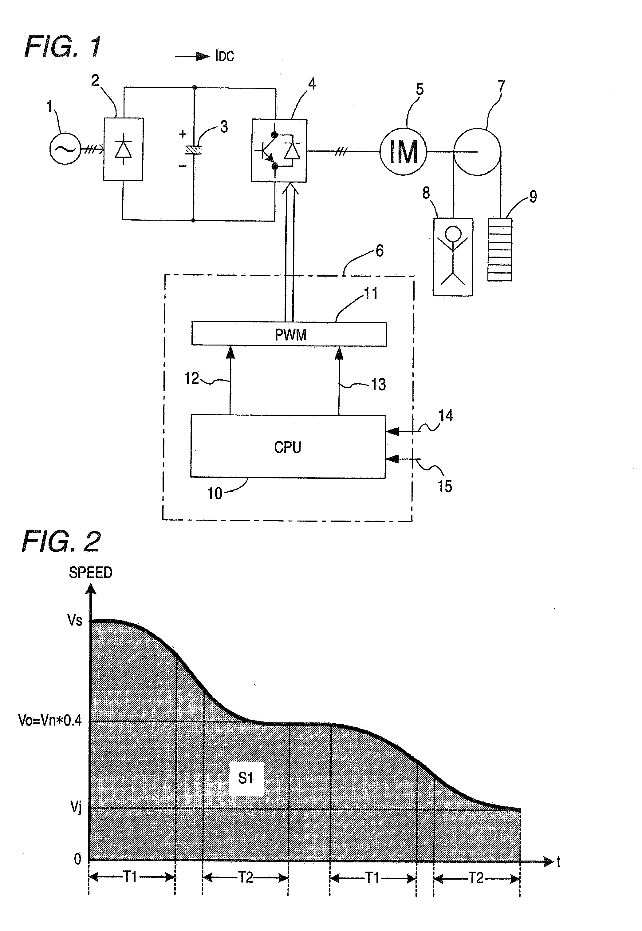
[0046]FIG. 3 is a diagram of an apparatus arrangement for indicating an embodiment mode of the present invention.
[0047] In this embodiment mode, a speed control apparatus of an elevator-purpose inverter is arranged by an AC power supply 1, a rectifier 2, a capacitor 3, a voltage type inverter main circuit 4, an induction motor 5, a control apparatus 6, a winding machine 7, a passenger car 8, and a balance weight 9. The rectifier 2 converts an AC voltage of the AC power supply 1 to a DC voltage. The capacitor 3 smooths either a full-wave rectification voltage or a half-wave rectification voltage, which are rectified by the rectifier 2. The voltage type inverter main circuit 4 inverts the DC voltage smoothed by the capacitor 3 into an AC voltage having a predetermined frequency and a predetermined voltage. The induction motor is driven by the AC voltage produced by the voltage type inverter main circuit 4. The control apparatus controls the frequency and the voltage of the voltage type inverter main circuit 4. The winding machine 7 is rotatably driven by the induction motor 5. A passenger car 8 is hung by one end of a wire rope suspended on the winding machine 7. The balance weight 9 is hung by the other end of the wire rope. The control apparatus 6 is further equipped with a CPU (central processing unit) 10, and a PWM (pulse width modulator) generating unit 11.
[0048] In this embodiment mode, an AC voltage of the AC power supply is converted into a DC voltage by the rectifier 2, and the rectified DC voltage is smoothed by the capacitor 3. This DC voltage is inverted into an AC voltage whose output frequency and output voltage are controlled by the voltage type inverter main circuit 4, and then, the AC voltage is applied to the induction motor 5 corresponding to a driving motor of the elevator. The controlling operations of both an operation frequency and an operation voltage is the inverter main circuit 4 are carried out based upon a gate pulse frequency control and a pulse width control by the control apparatus 6. As a result of this control operation, the operation speed of the induction motor 5 is controlled. The induction motor 5 drives via the winding machine 5 loads of the passenger car 8 and the balance weight 9.
[0049] The control apparatus 6 constituted by the CPU 10 as a major unit produces a speed pattern which owns a predetermined acceleration speed, a predetermined deceleration speed, and also a constant speed time in response to an elevating distance so as to acquire an inverter drive frequency and an amplitude of a voltage, and obtains a PWM wave gate pulse in response to these acquired frequency and voltage. This PWM wave gate pulse is supplied to the PWM generating unit 11.
[0050] A speed correcting control member provided with the CPU 10 performs control operations in such a manner that even when a set value of an arbitrary frequency (Vs) is changed, the passenger car 8 of the elevator is operated in a constant speed at an intermediate frequency (Vo) so as to adjust an elevating distance; and thereafter, when the elevator passenger car 8 reaches the deceleration starting position, the elevator passenger car 8 is automatically decelerated in a constant deceleration speed up to the leveling frequency (Vj).
[0051]FIG. 2 indicates an operation example as to the embodiment mode of the present invention. FIG. 3 shows an operation flow after the present invention is carried out. In FIG. 3, symbol S100 shows a step for judging as to whether or not the elevator passenger car is under drive condition. Symbol S110 represents a step for calculating a reference elevating distance (S) from Vn to Vj. Symbol S120 shows a step for judging as to whether the leveling frequency “Vj” is “ON”, or “OFF.” Symbol S130 indicates a step for operating the elevator passenger car 8 at an arbitrary frequency “Vs.” Symbol S140 represents a step for judging as to whether or not the leveling frequency Vj is selected during driving operation at the arbitrary frequency Vs. In a step S140, when this function is valid (19), the elevator passenger car 8 is directly decelerated up to the leveling frequency Vj. Symbol S150 is a step for driving the elevator passenger car 8 at the leveling frequency Vj. Symbol S160 indicates a step for subtracting an elevating distance at the present speed from the elevating distance (S). Symbol S170 shows a step for calculating an elevating distance (S1) from the present speed up to Vj. Symbol S180 represents a step for comparing the magnitude of the elevating distance (S1) with the magnitude of the elevating distance (S). Symbol S190 indicates a step for operating the elevator passenger car 8 at the intermediate frequency (Vo) (operated at 40% of Vn).
[0052] The CPU 10 monitors as to whether the elevator passenger car 8 is under drive condition, or under stop condition (step S100). Normally, the elevator passenger car 8 is controlled in such a manner that the elevator passenger car 8 is driven at the arbitrary frequency (Vs) under drive condition (S120 and S130). When the elevator passenger car 8 reaches the deceleration starting point, a signal of the leveling frequency (Vj) instruction is supplied to the CPU 10 when being reached to the deceleration starting point, and at this signal timing, the elevator passenger car 8 is operated at a constant speed at the intermediate frequency (Vo) so as to adjust an elevating distance (S190), and is decelerated up to the leveling frequency (Vj) at a deceleration speed which is equal to the deceleration speed of the intermediate frequency (Vo) (S150).
[0053] An elevating distance corresponds to an area of a region (S) shown in fig. 6, and is previously calculated during stopping operation (S110). The elevating distance (S) from the reference frequency (Vn) up to the leveling frequency (Vj) may be calculated based upon the below-mentioned formula. S = Tdec 2 fmax ( Vn 2 - Vj 2 ) + VnT 1 + VjT 2 2 [ Formula 1 ]
[0054] In this formula 1, symbol “Tdec”: deceleration time, symbol “fmax”: maximum frequency, symbol “Vn”: reference frequency, symbol “Vs”: arbitrary frequency, symbol “Vj”: leveling frequency, symbol “T1”: S-shaped characteristic time when deceleration is commenced, and symbol “T2”: S-shaped characteristic time when deceleration is completed.
[0055] A method of calculating this elevating distance “S” will now be explained more concretely with reference to FIG. 4 and FIG. 5.
[0056] In FIG. 4, an elevating distance until the elevator passenger car 8 is decelerated from Vn to Vj becomes an area of a meshed portion. In order to calculate this area, first of all, as indicated in FIG. 5, an S-shaped characteristic will now be considered. During the S-shaped characteristic time T1 of FIG. 5, since an increase of acceleration becomes constant, a speed “f” is expressed by the following formula. f = 1 T 1 × fmax Tdec × t [ Formula 2 ]
[0057] As a result, a speed during the time T1 of FIG. 4 is expressed by the following formula: f ( t ) = ∫ 0 t f ⅆ t = ∫ 0 t ( 1 T 1 × fmax Tdec × t ) ⅆ t = fmax 2 Tdec × t 2 T 1 [ Formula 3 ]
[0058] After the time T1 has elapsed, acceleration becomes constant, the speed becomes a straight line which is increased with an inclination of “fmax/Tdec”, and a section T2 becomes a parabola whose direction is opposite to that of the section T1. In order to calculate these areas, an S-shaped characteristic section is considered by being resolved. A function of a section “A” is expressed by the following formula. f 1 ( t ) = Vn - fmax 2 Tdec × t 2 T 1 [ Formula 4 ]
[0059] As a consequence, an area “A” of this section “A” is given by the below-mentioned formula: A = ∫ 0 T 1 f 1 ( t ) ⅆ t = ∫ 0 T 1 Vn ⅆ t - fmax 2 Tdec × T 1 ∫ 0 T 1 t 2 ⅆ t = VnT 1 - fmax 2 Tdec × T 1 T 1 3 3 = VnT 1 - fmax × T 1 2 6 Tdec [ Formula 5 ]
[0060] A function of a section “C” is given by the following formula: f 2 ( t ) = Vj + fmax 2 Tdec × t 2 T 2 [ Formula 6 ]
[0061] As a consequence, an area “C” of the section “C” is given by the following formula: C = ∫ 0 T 2 f 2 ( t ) ⅆ t = VjT 2 + fmax × T 2 2 6 Tdec [ Formula 7 ]
[0062] A section “B” may be obtained by calculating an area of a trapezoid, the upper bottom of which is VT2, the lower bottom of which is VT2, and the height of which is T3. Since the section “B” is changed in a leaner manner by the below-mentioned inclination: - fmax Tdec , [ Formula 8 ]
the height T3 is given by the following formula: T 3 = Tdec fmax ( VT 1 - VT 2 ) [ Formula 9 ]
[0063] Also, “VT1” and “VT2” are given by the following formula: VT 1 = f 1 ( T 1 ) = Vn - fmax 2 Tdec × T 1 2 T 1 = Vn - fmax 2 Tdec T 1 VT 2 = f 2 ( T 2 ) = Vj + fmax 2 Tdec T 2 [ Formula 10 ]
[0064] As a result, “B” is given as follows: B = ( VT 1 + VT 2 ) × T 3 2 = Tdec 2 f max ( VT 1 + VT 2 ) ( VT 1 - VT 2 ) = Tdec 2 f max { ( Vn - f max 2 Tdec T 1 ) + ( Vj + f max 2 Tdec T 2 ) } { ( Vn - f max 2 Tdec T 1 ) - ( Vj + f max 2 Tdec T 2 ) } = Tdec 2 f max { Vn + Vj - f max 2 Tdec ( T 1 - T 2 ) } { Vn - Vj - f max 2 Tdec ( T 1 + T 2 ) } = Tdec 2 f max { Vn 2 - VnVj - Vnf max 2 Tdec ( T 1 + T 2 ) + VnVj - Vj 2 - Vjf max 2 Tdec ( T 1 + T 2 ) - Vnf max 2 Tdec ( T 1 - T 2 ) + Vjf max 2 Tdec ( T 1 - T 2 ) + f max 2 4 Tdec 2 ( T 1 + T 2 ) ( T 1 - T 2 ) ) } = Tdec 2 f max ( Vn 2 - Vj 2 ) - Vn 4 ( T 1 + T 2 ) - Vj 4 ( T 1 + T 2 ) - Vj 4 ( T 1 - T 2 ) + Vj 4 ( T 1 - T 2 ) + f max 8 Tdec ( T 1 2 - T 2 2 ) = Tdec 2 f max ( Vn 2 - Vj 2 ) - VnT 1 + VjT 2 2 + f max 8 Tdec ( T 1 2 - T 2 2 ) [ Formula 11 ]
[Formula 12]
[0065] Since S=A+B+C, the elevating distance “S” is given as follows: S = A + B + C = VnT 1 - f max 6 Tdec T 1 2 + Tdec 2 f max ( Vn 2 - Vj 2 ) - VnT 1 + VjT 2 2 + f max 8 Tdec ( T 1 2 - T 2 2 ) + VjT 2 + f max 6 Tdec T 2 2 = Tdec 2 f max ( Vn 2 - Vj 2 ) + 2 ( VnT 1 + VjT 2 ) 2 - VnT 1 + VjT 2 2 - f max 6 Tdec ( T 1 2 - T 2 2 ) + f max 8 Tdec ( T 1 2 - T 2 2 ) = Tdec 2 f max ( Vn 2 - Vj 2 ) + VnT 1 + VjT 2 2 - f max 24 Tdec ( T 1 2 - T 2 2 )
[0066] In this formula, assuming now that T1 is nearly equal to T2, the below-mentioned formula 13 can be neglected: f max 24 Tdec ( T 1 2 - T 2 2 ) [ Formula 13 ]
[0067] Based upon the above-explained conditions, an elevating distance “S” when the elevator passenger car 8 is decelerated with an S-shaped characteristic from Vn to Vj is given by the following formula (step S110): S = Tdec 2 f max ( Vn 2 - Vj 2 ) + VnT 1 + Vj T 2 2 [ Formula 14 ]
[0068] Also, as to an area of the region (S1) shown in FIG. 2, an elevating distance (S1) from the arbitrary frequency (Vs) up to the leveling frequency (Vi) may be calculated by the following formula (step S170): S 1 = Tdec 2 f max ( Vs 2 - Vj 2 ) + VsT 1 + VjT 2 2 [ Formula 15 ]
[0069] In the case that an elevating distance is S1180), the elevator passenger car 8 is driven in Vo (S190). In a next scan, a distance over which the elevator passenger car 8 is advanced at the present speed (intermediate frequency Vo) is subtracted from the elevating distance “S” which is calculated during stopping operation (S160).
S=S−VoTs [Formula 16]
[0070] (symbol “Ts” indicates sampling time).
[0071] After the driving operation of the elevator passenger car 8 waits at the intermediate frequency Vo until the elevating distance “S1” becomes equal to “S”, the elevator passenger car 8 is decelerated up to the leveling frequency (Vj), so that the elevating distances “S” and “S1” can be made equal to each other.
[0072] In other words, the equal condition between the elevating distances “S” and “S1” can be realized by automatically switching the frequency instructions based upon the time “t” in such a manner that the below-mentioned formula can be satisfied:
S=S1+ΣVo·t [Formula 17]
[0073] In the embodiment mode of the present invention, the operation time at the intermediate frequency (Vo) is adjusted in such a manner that the elevating distance from Vs up to Vj may become equal to the reference elevating distance “S.”
[0074] In other words, while the elevator passenger car 8 is driven at the arbitrary frequency Vs ( 130, when the leveling frequency Vj is selected in the step S140, the elevator passenger car 8 is once decelerated up to 40% (Vo) of the reference frequency Vn in the step S190. After the drive operation of the elevator passenger car 8 waits until such a time that the elevating distance until the frequency reaches the leveling frequency Vj becomes “S” in the step S180, the elevator passenger car 8 is decelerated up to the leveling frequency Vj in the step S150.
[0075] While the elevator passenger car 8 is driven at the lower speed than 40% of the reference frequency Vn, when the leveling frequency Vj is selected, after the driving operation waits until such a time that the elevating distance at this speed until the frequency reaches the leveling frequency Vj becomes “S”, the elevator passenger car 8 is decelerated up to the leveling frequency Vj.
[0076] While the driving operation of the elevator passenger car 8 is accelerated, when the leveling frequency Vj is selected, operations are different from each other in response to frequency instructions issued at this time.
[0077] When the frequency instruction>(40% of Vn), after the drive operation of the elevator passenger car 8 waits until such a time that the elevating distance until the frequency reaches the leveling frequency Vj at 40% of the reference frequency Vn becomes “S”, the elevator passenger car 8 is decelerated up to the leveling frequency Vj. When the frequency instruction 8 waits until such a time that the moving time until the frequency reaches the leveling frequency Vj at this frequency becomes “S”, the elevator passenger car 8 is decelerated up to the leveling frequency Vj.
[0078] Thus, the elevating distances “S” and “S1” can be obtained equal to each other in the above-explained manner. In the case that the elevator passenger car is moved over the short distances such as a next floor, since the frequency is changed into the arbitrary frequency, the comfortable conditions of the passenger car can be improved, which are deteriorated by the changes in gravity and the vibrations. The elevator passenger car is driven in the constant speed at the intermediate frequency so as to adjust the elevating distance. As a result, such a problem that the floor arriving position is largely deviated can be solved.
INDUSTRIAL APPLICABILITY
[0079] The present invention can be utilized in speed control operations as to the inverter drive type elevator-purpose induction motor capable of improving the comfortable conditions of the elevator passenger car, which are deteriorated by the changes in gravity and the vibrations since the elevator passenger car is rapidly decelerated, and also capable of improving the floor arriving precision.