
Three dimensional dielectrophoretic separator and methods of use

a dielectrophoretic separator and three-dimensional technology, applied in the direction of fluid pressure measurement, liquid/fluent solid measurement, peptide, etc., can solve the problems of thermal convection disturbance, thermal convection pushing off, and the separation of unseparated cells is difficult to achieve, so as to minimize the non-specific adhesion of cells and achieve the separation of desired cells. uniform, the effect of extending the dielectrophoretic for

Inactive Publication Date: 2007-08-16
GAMIDA FOR LIFE
View PDF2 Cites 12 Cited by
  • Summary
  • Abstract
  • Description
  • Claims
  • Application Information

AI Technical Summary

Benefits of technology

[0026] Still a further object of the present invention is to provide devices and methods for providing uniform separation of desired cells with minimized non-specific adhesion of cells to the flow chamber and / or electrodes.
[0027] Yet a further object of the present invention is to provide devices and methods for three-dimensional separation of desired cells without the disruption associated with a washing step.
[0028] Another object of the present invention is to provide electronic arrays capable of extending dielectrophoretic forces substantially throughout a flow chamber so as to facilitate efficient separation without the need for a washing protocol.

Problems solved by technology

These prior devices have several problems, including the following.
A first problem is that both separated and unseparated cells bind nonspecifically to the exposed glass surface of the slide and to the exposed electrode surfaces.
A second problem is that the volume of the flow chamber (several hundred microliters) is so large that thermal convection disturbs and pushes off cells initially retained by the electrodes.
A third problem is that washing off any undesired cells is not easily accomplished without disturbing the cells that are desirably retained on the electrodes, as the desired cells and electrodes stand in the way of fluidic flow and, hence, block the wash flow containing any undesired cells.
These conventional electronic lysis techniques have several problems, including the following.
A first problem is that the electronic lysis conditions specified by commercial macro-device do not release DNA molecules of high molecular weight (larger than 20 Kb) because the high molecular weight DNA molecules do not fit through the pores created in the cell membrane by the prior lysing methods.
A second problem is that some nucleic acids originally released in the lysis chamber are lost due to their non-specific binding to the surface of the lysis chamber.
A third problem is that the conventional electronic lysis macrodevice works as a stand alone unit such that both dielectrophoretic cell separation and electronic lysis cannot be performed on the same module.
These conventional preparation and processing techniques have several problems, including the following.
A first problem is that the steps of sample preparation and processing are typically performed separately and apart from the other main steps of hybridization, detection and analysis.
In addition, most of these techniques involve carrying out numerous operations (e.g., pipetting, centrifugations, electrophoresis) on a large number of samples.
They are often complex and time consuming, and generally require a high degree of skill.
Many a technique is limited in its application by a lack of sensitivity, specificity, or reproducibility.
For example, these problems have limited many diagnostic applications of nucleic acid hybridization analysis.
Although dielectrophoresis retention has been successfully demonstrated for isolating cancer cells, bacteria, or CD34+ stem cells from blood, two practical deficiencies minimize the effectiveness of this technique in biomedical applications.
However, with increasing distance (e.g., more than 10 μm) from the electrode plan, the electric field decays rapidly and the non-uniformity of the field distribution becomes smaller.
The dielectrophoretic forces in such two-dimensional systems are only able to collect the cells of interest that are located close to the electrode plane, while cells floating well above the electrode plane can be lost during washing.
Second, the dielectrophoretic forces acting on the cells are not the uniform due to the heterogeneous properties among different cells types.
Therefore, cells that experience smaller dielectrophoretic properties may be lost during washing steps because the dielectrophoretic forces are not strong enough to hold the cells against the fluid-flow forces.
Generally, the prior art processes have been extremely labor and time intensive.
Multiple steps requiring human intervention either during the process or between processes are suboptimal in that there is a possibility of contamination and operator error.
Further, the use of multiple machines or complicated robotic systems for performing the individual processes is often prohibitive except for the largest laboratories, both in terms of the expense and physical space requirements.
However, for the reasons stated above, these techniques are limited and lacking.
These various approaches are not easily combined to form a system which can carry out a complete DNA diagnostic assay.
Despite the long-recognized need for such a system, no satisfactory solution has been proposed previously.

Method used


Image

  • Three dimensional dielectrophoretic separator and methods of use
  • Three dimensional dielectrophoretic separator and methods of use
  • Three dimensional dielectrophoretic separator and methods of use

Examples


Embodiment Construction

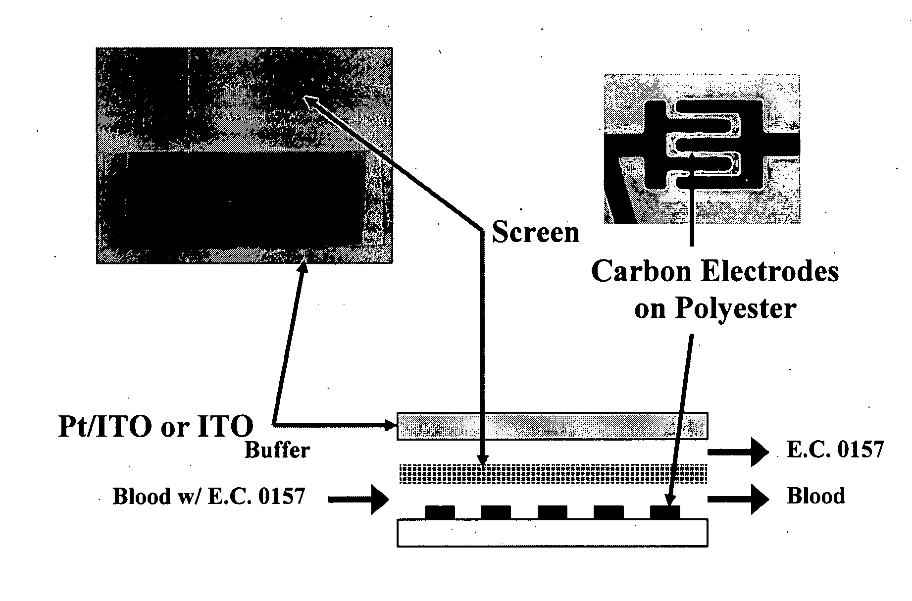
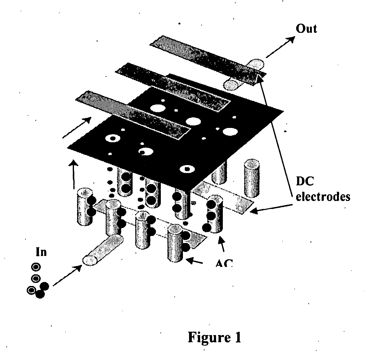
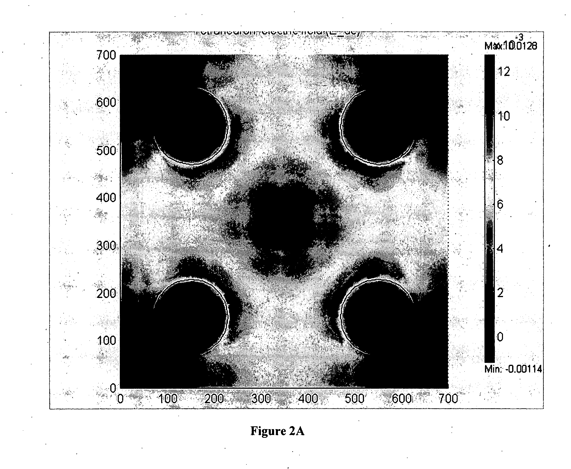
[0048] The present invention comprises devices and methods for performing separation of cell particles by three-dimensional dielectrophoresis, which can be conducted on a single bioelectronic chip.

[0049] The basic theory of dielectrophoresis, motion of particles with induced polarization under non-uniform electric field, has been extensively studied. See, e.g., R. Pethig, “Dielectrophoresis: Using Inhomogeneous AC Electrical Fields To Separate and Manipulate Cells”, Crit. Rev. Biotech, 16:331-48 (1996); X. Wang, et al., “A Unified Theory of Dielectrophoresis and Travelling Wave Dielectrophoresis”, J. Phys. D: Appl. Phys., 27:1571-74 (1994); G. Fuhr, “Cell Manipulation and Cultivation Under AC Electric Field Influence in Highly Conductive Culture Media”, Biochim. Biophys. Acta 1158:40-46 (1993); and M. Washizu, “Molecular Dielectrophoresis of Biopolymers”, IEEE Trans. Industry Applicat. 30:835-43 (1994). The dielectrophoresis phenomenon can be generally described by energy potential...


PUM

PropertyMeasurementUnit
Volumeaaaaaaaaaa
Volumeaaaaaaaaaa
Electric potential / voltageaaaaaaaaaa

Abstract

Devices and methods for performing separation of cell particles by dielectrophoresis in three dimensions. In one embodiment the device comprises a flow chamber having microfabricated chip with a plurality of vertical and horizontal electrodes, which may be coated with a protective layer to prevent direct contact between any electrode and a sample. The horizontal electrodes are in electrical communication with a DC or an AC power source, while the vertical electrodes are in electrical communication with an AC power source.

Description

CROSS REFERENCE TO RELATED APPLICATIONS [0001] This patent application claims priority to U.S. patent application Ser. No. 60 / 749,760, filed Dec. 13, 2005, the specification of which is incorporated herein by reference in its entirety.FEDERAL FUNDS STATEMENT [0002] This invention was reduced to practice with funds from NIH Project R43 AI 54003-01. The Government may have certain rights to this invention.FIELD OF THE INVENTION [0003] This invention relates to devices and methods for performing active, molecular and biological sample preparation and diagnostic analyses. It relates generally to devices and methods for electronic cell separation; and more specifically, to devices and methods for achieving three dimensional separation of cells or other bioparticles from biological samples using dielectrophoresis, which can be conducted on a single bioelectronic chip (e.g. in an integrated assay system). These manipulations are useful in a variety of applications, including, for example, ...

Claims


Application Information

Patent Timeline
IPC IPC(8): B03C5/02
CPCB03C5/026B03C5/005G01N27/447
Inventor HODKO, DALIBORHUANG, YINGSMOLKO, DANIEL D.
Owner GAMIDA FOR LIFE
Learn More