Method and system for filtering sediment-bearing fluids

a technology of sediment-bearing fluid and filter element, which is applied in the direction of filtration separation, membranes, separation processes, etc., can solve the problems of inefficiency and potential failure of the pumping system, severe damage to the pumping system valve and the pumping system, and the accumulation of particulate material in the filter elemen

Inactive Publication Date: 2007-08-16
GORDON ROBERT R
View PDF35 Cites 17 Cited by
  • Summary
  • Abstract
  • Description
  • Claims
  • Application Information

AI Technical Summary

Benefits of technology

[0008] The system, method, and devices of the invention each have several aspects, no single one of which is solely responsible for its desirable attributes. Without limiting the scope of this invention, its more prominent features will now be discussed briefly. After considering this discussion, and particularly after reading the section entitled “Detailed Description of the Embodiments of the Invention” one will understand how the features of this invention provide advantages that include water filtration systems having lowered maintenance costs.

Problems solved by technology

Often, the fluid contains sand and other abrasive particles that are a constant cause of inefficiency in and potential failure of the pumping systems.
For example, sand can cause severe damage to the pump and valves in the pumping system.
However, the particulate material often becomes entrapped in the filter element.
This can be a timely and inconvenient process.
Pumps with intricate backwashing systems have been designed, but these are often expensive and cannot be used to retrofit existing systems.
As a result, many pumps are generally operated without any filter and therefore experience early pump failure and extensive and costly down time.
While this has proven successful, it is also expensive due to the disposal and / or treatment of resulting concentrate of contaminants.

Method used


Image

  • Method and system for filtering sediment-bearing fluids
  • Method and system for filtering sediment-bearing fluids
  • Method and system for filtering sediment-bearing fluids

Examples


Embodiment Construction

” one will understand how the features of this invention provide advantages that include water filtration systems having lowered maintenance costs.

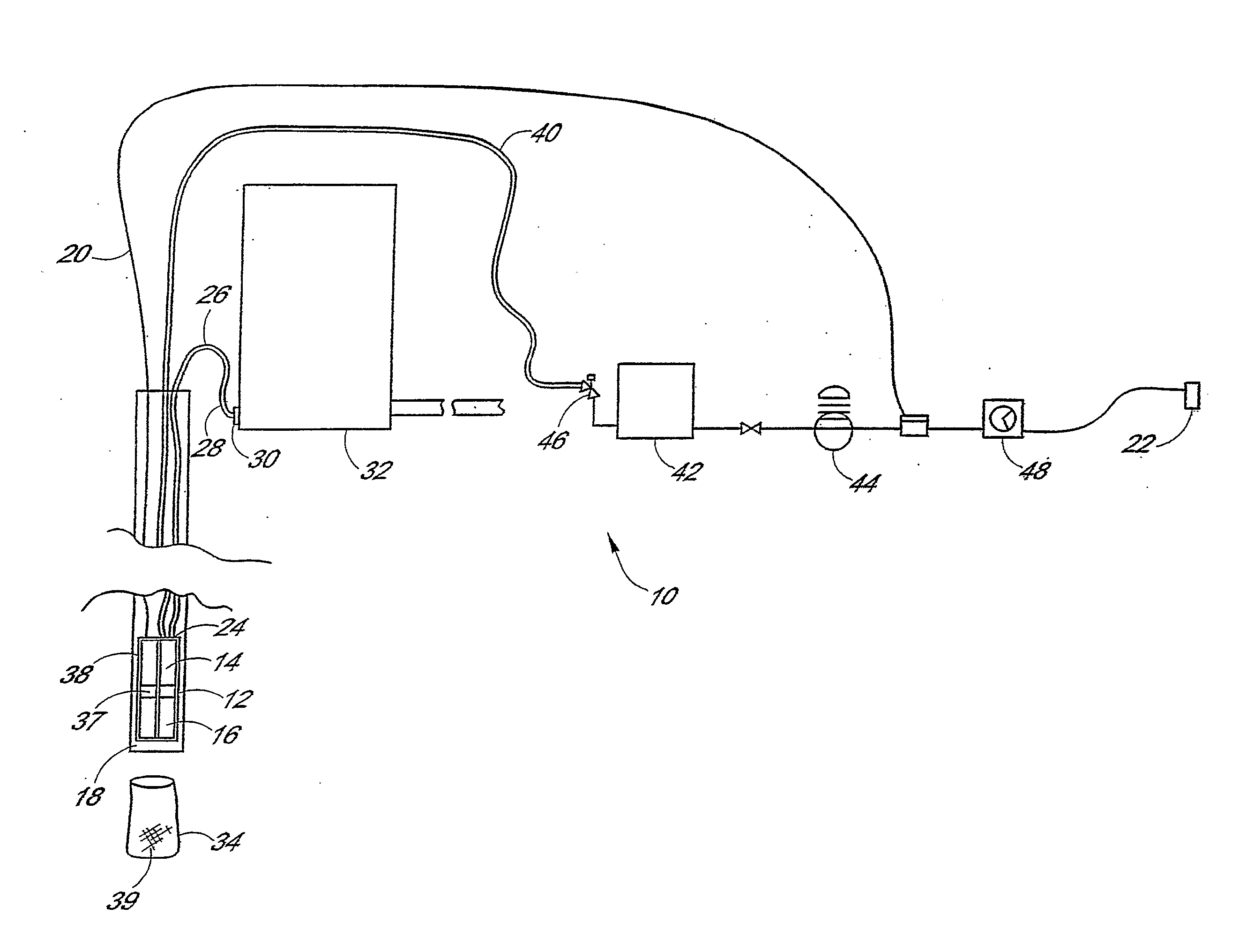
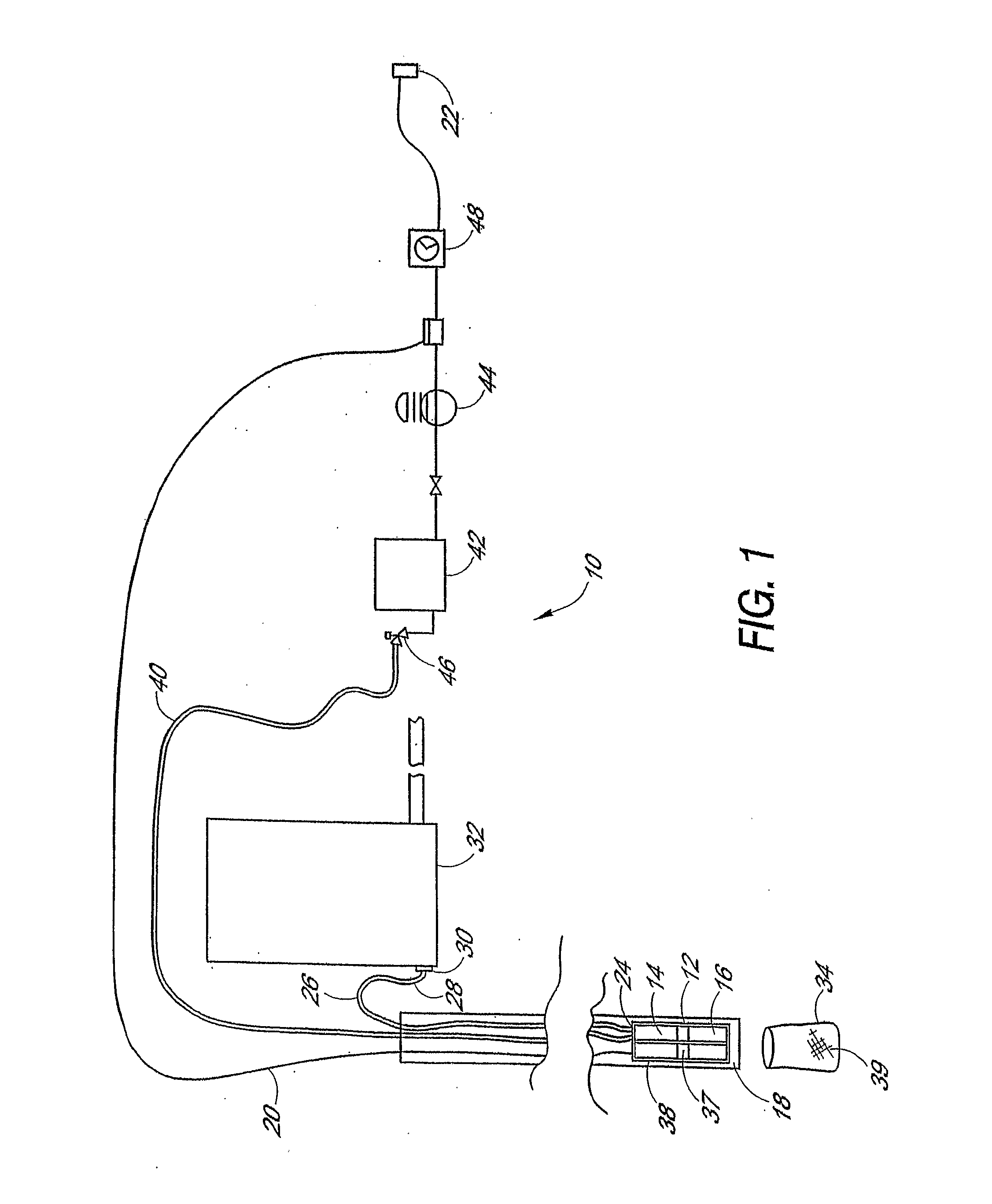
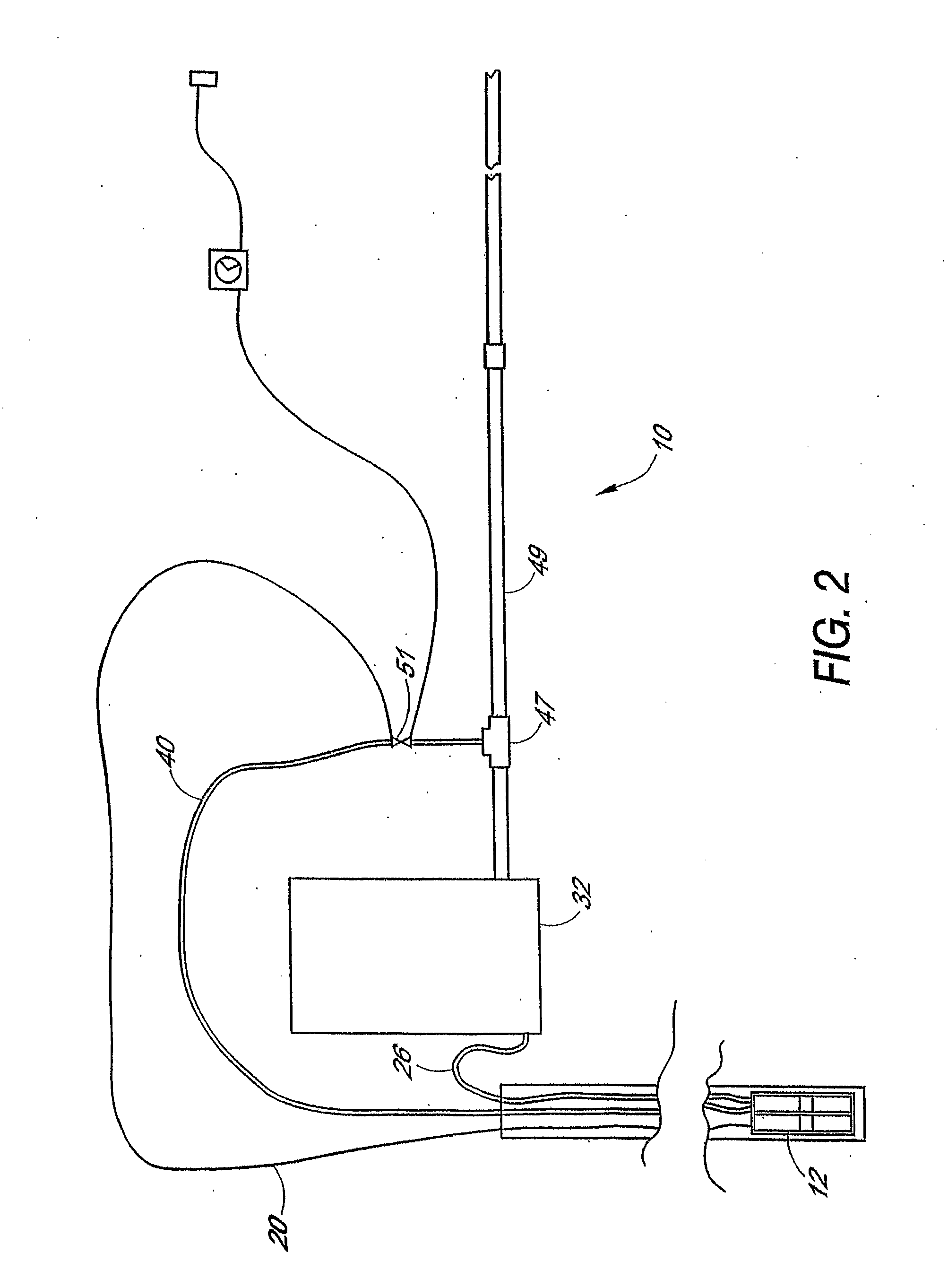
[0009] One embodiment is a self-cleaning filtration system for filtering a fluid flow. The system may include a cage and one or more filters disposed within the cage. At least one pipe is configured to receive water through each filter. The cage may include a non-permeable leading member configured to meet and divert the fluid flow. The filters are configured to be placed downstream of the leading member. The cage may also include a trailing member and a bottom member configured to secure the cage. At least one side member may coupled to the leading and trailing members and coupled to the bottom member. The side members are angled inwardly with respect to a centroid defined by the cage from the leading member to the trailing member.

[0010] Another embodiment is a method of pumping fluid from a flow of fluid. The method comprises diverting...


PUM

PropertyMeasurementUnit
internal diametersaaaaaaaaaa

Abstract

A self-cleaning, back-washable filter apparatus (1700) and method for use with a pumping apparatus (1734). In one embodiment, the filter apparatus is at least partially immersed in fluid. A sediment removal system is disclosed for removing sediment from around a filter apparatus. The sediment removal system comprises a plurality of venturi jets (1307) configured to force sediment particles through a discharge line and away from the inlet to a filter apparatus. A filtering system is configured to direct a flow of fluid generally parallel to the surface of the filter (1720), which may be a cross-flow filter, to prevent clogging or fouling. In one embodiment, the filtering system is configured to direct the flow of fluid in a spiral flow around the surface of the filter A method for filtering a flow of fluid comprises directing a flow of fluid generally parallel to the surface of a filter to prevent clogging or fouling of the filter A method for filtering a flow of fluid is also disclosed, comprising vibrating a filter by applying a flow of fluid to the filter.

Description

BACKGROUND OF THE INVENTION [0001] 1. Field of the Invention [0002] The invention relates to a filter apparatus and more particularly to a self-cleaning, back-flushable filter for removing particulate material from a pump intake. [0003] 2. Description of the Related Art [0004] Submersible pumps are often lowered into fluid supplies such as those found in well casings or ponds in order to remove the fluid that is found there. Often, the fluid contains sand and other abrasive particles that are a constant cause of inefficiency in and potential failure of the pumping systems. For example, sand can cause severe damage to the pump and valves in the pumping system. [0005] Many types of filters have been designed for use with submersible pumps. Such filters have typically included a filter element designed to screen particulate material from the pump intake. However, the particulate material often becomes entrapped in the filter element. The quantity of particulate material collected on th...

Claims


Application Information

Patent Timeline
Patent Type & Authority Applications(United States)
IPC IPC(8): B01D61/00
CPCB01D29/115B01D61/08C02F1/444C02F1/441B01D2321/2058B01D61/10B01D61/18B01D61/20B01D63/06B01D63/065B01D63/16B01D65/02B01D2315/06B01D2321/04B01D29/66B01D29/68B01D29/906
Inventor GORDON, ROBERT R.
Owner GORDON ROBERT R
Why Eureka
Try Eureka