Electromagnetic switch and related manufacturing method

a manufacturing method and technology of electromagnetic switches, applied in the field of electromagnetic switches, can solve problems such as the increase in production costs, and achieve the effect of simplifying assembly steps and increasing productivity

Inactive Publication Date: 2007-08-16
DENSO CORP
View PDF17 Cites 11 Cited by
  • Summary
  • Abstract
  • Description
  • Claims
  • Application Information

AI Technical Summary

Benefits of technology

[0043]In such a case, the thin plate placed in the outermost layer of the disc section can have the same shape as those of the other thin plates, providing increased productivity and simplified assembling steps.

Problems solved by technology

Therefore, the press-out retaining lug 114 needs to be formed on the thin plate 112a placed on the outermost layer of the disc section 110 and, hence, the thin plate 112a has a configuration different from the other thin plates 112, causing an increase in production cost.

Method used


Image

  • Electromagnetic switch and related manufacturing method
  • Electromagnetic switch and related manufacturing method
  • Electromagnetic switch and related manufacturing method

Examples


first embodiment

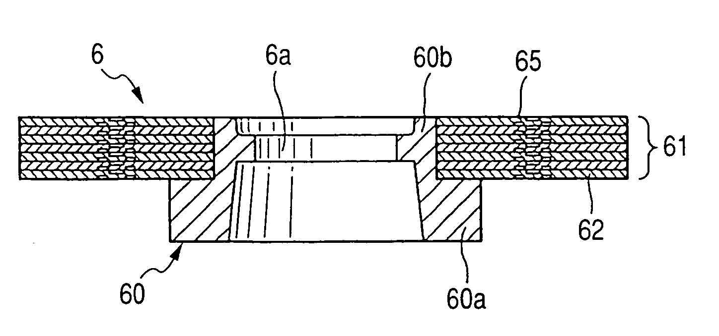
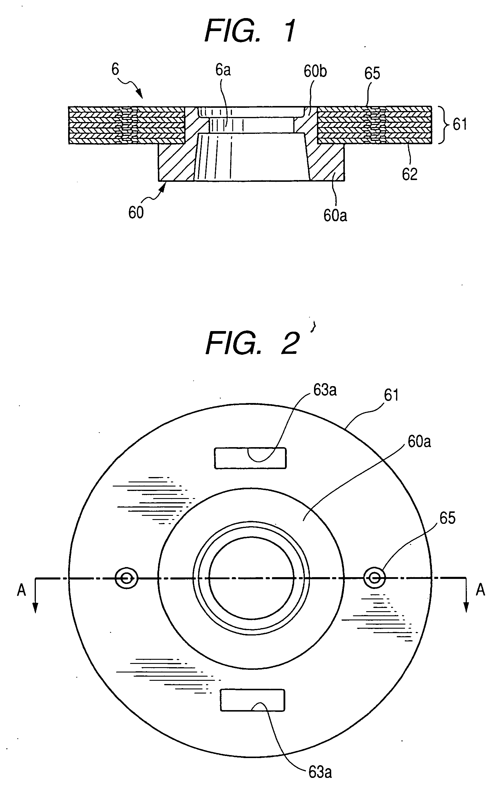
[0057]FIG. 1 is a cross sectional view, taken on line B-B of FIG. 2, which shows a stator core 6; FIG. 2 is a plan view of the stator core 6 as viewed from a base section 60; and FIG. 6 is a cross sectional view of an electromagnetic switch 1.

[0058]The electromagnetic switch 1 (see FIG. 6) of the first embodiment, used in a starter (not shown) for starting up an engine of a motor vehicle, has a function to close a main contact MC disposed in a motor energizing circuit (herein referred to as a motor circuit). As shown in FIG. 6, the electromagnetic switch 1 comprises a solenoid 2 with which an electromagnet is formed, and a switch cover 3 fixedly secured to the solenoid 2.

[0059]The solenoid 2 comprises a switch case 4 forming a yoke, an electromagnetic oil 5 received inside the switch case 4, a stationary core 6 that is magnetized upon energizing the electromagnetic oil 5, a plunger (movable contact) 8 slidably inserted to an interior of the electromagnetic oil 5 via a sleeve, and a ...

second embodiment

[0088]FIG. 8 is a cross sectional view of a stationary core 6A of a second embodiment according to the present invention, taken on line A-A of FIG. 9 passing across a center 0, which is a plan view showing the stationary core 6A.

[0089]With the second embodiment, the stationary core 6A includes the base section 60 and a disc section 61A that includes plural thin disc plates 62A secured to each other by means of positioning pins 26.

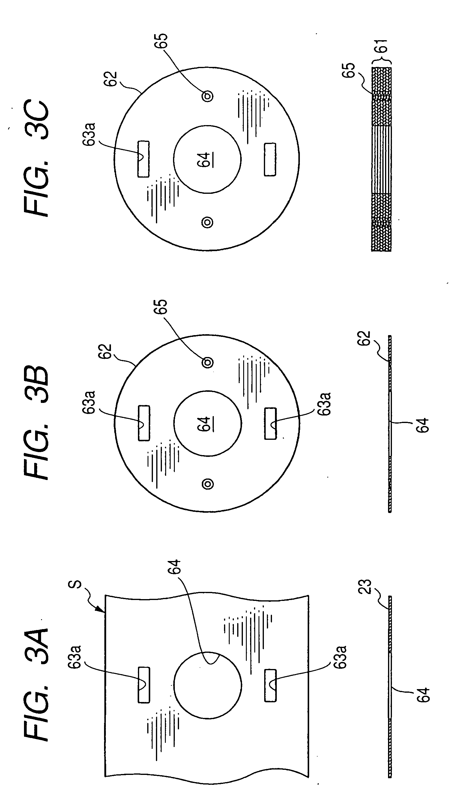
[0090]As shown in FIG. 9, the thin disc plate 62A is formed with two oblong through-bores 63a in first radially symmetric positions with respect to the center 0 and two small apertures 66 in second radially symmetric positions with respect to the center 0 and substantially perpendicular to an axis passing across centers of the oblong through-bores 63a.

[0091]Before assembling the disc section 61A onto the base portion 60, plural disc plates 62A are stacked and fixedly secured to each other under a condition where the plural disc plates 62A are positioned by...

third embodiment

[0097]FIG. 10 is a cross sectional view of a stationary core 6B of a third embodiment according to the present invention.

[0098]With the third embodiment, the stationary core 6B comprises a base section 60 and a disc section 61B that includes plural disc plates 62B that are fixedly secured to each other by means of rivets 27 press fitted to small apertures 26B formed in the disc plates 62B. The use of the rivets 27 enable the plural disc plates 62B to be reliably fixed in a stacked direction (in a vertical direction).


PUM


Abstract

An electromagnetic switch and related manufacturing method are disclosed having an electromagnetic coil creating an electromagnet when energized, a stationary core associated with the electromagnetic coil and operative to be magnetized when the electromagnet is created, one set of stationary contacts disposed in areas away from the stationary core, and a plunger carrying thereon a movable contact and operative to move toward the stationary contacts to close the same when the stationary core is magnetized by the electromagnet. The stationary core includes a base section and a disc section assembled to the base section. The disc section includes a plurality of stacked thin plates, fixedly secured to each other by fixing means, which have through-openings extending to each other in a circumferential direction in communication with each other to form a coil takeout opening through which an end portion of the electromagnetic coil is extracted.

Description

CROSS REFERENCE TO RELATED APPLICATIONS[0001]This application is related to Japanese Patent Application No. 2006-35381 and No. 2006-220136, filed on Feb. 13, 2006 and Aug. 11, 2006, respectively, the contents of which are hereby incorporated by reference.BACKGROUND OF THE INVENTION[0002]1. Technical Field of the Invention[0003]The present invention relates to electromagnetic switches for use in starters for starting up engines and, more particularly, to an electromagnetic switch adapted to open or close electrical contacts disposed in an energization circuit of a starter motor.[0004]2. Description of the Related Art[0005]Various attempts have heretofore been to provide electromagnetic switches for use in starting up starter motors, with one of such electromagnetic switches being disclosed in U.S. Pat. No. 6,281,770 (Japanese Unexamined Patent Application Publication No. 2002-524826).[0006]With such a related art, the electromagnetic switch includes an electromagnetic coil and a stat...

Claims


Application Information

Patent Timeline
Patent Type & Authority Applications(United States)
IPC IPC(8): H01H67/02
CPCH01H50/36H01H51/065H01H50/443
Inventor TSUKADA, MIKIOUSAMI, SHINJI
Owner DENSO CORP
Why Eureka
Try Eureka