Multi-user autostereoscopic display with position tracking

a multi-user, position tracking technology, applied in surveying, navigation, instruments, etc., can solve the problems of multi-user operation, difficult practical realization of such a multi-user display, and disadvantages of using a diffuser plate, so as to achieve low cost, low cost, and low labor intensity

Inactive Publication Date: 2007-08-16
SEEREAL TECHNOLOGIES
View PDF8 Cites 151 Cited by
  • Summary
  • Abstract
  • Description
  • Claims
  • Application Information

AI Technical Summary

Benefits of technology

[0026] The present invention relates to an autostereoscopic display that can be used by several observers simultaniously, a so-called multi-user display, controlled by a tracking and image controller, said display being characterised by low cost and little labour for the individual components and their alignment, flat design, possibility of replacing opt

Problems solved by technology

However, it is disadvantageous to use a diffuser plate as it generally prevents multi-user operation, since the diffuser plate with its multitude of secondary light sources is represented in periodical continuation through the second lenticular.
A practical realisation of such a multi-user display is rather difficult, because a high-resolution shutter is needed.
Further, matching lens elements, shutter openings and pixels of the image matrix requires extreme precision when manufacturing the components and when aligning them during assembly.
Already little deviations in pixel or segment dimensions or slight misalignment may lead to functional faults.
Further, great resistance of the assembled display to ambient influences, such as temperature fluctuation or vibration, would be required.
Another major disadvantage is represented by the fact that display components cannot be replaced individually.
The disadvantages of this device are a low brightness, because only the light of a locally selectable point light source is available for illuminating the entire image, a large imaging lens and a great d

Method used


Image

  • Multi-user autostereoscopic display with position tracking
  • Multi-user autostereoscopic display with position tracking
  • Multi-user autostereoscopic display with position tracking

Examples


Embodiment Construction

[0049] The autostereoscopic multi-user display according to this invention is described with the help of embodiments and illustrated in the accompanying FIGS. 2-7. Identical functional elements of the autostereoscopic multi-user display according to this invention are denoted by same reference numerals in all figures.

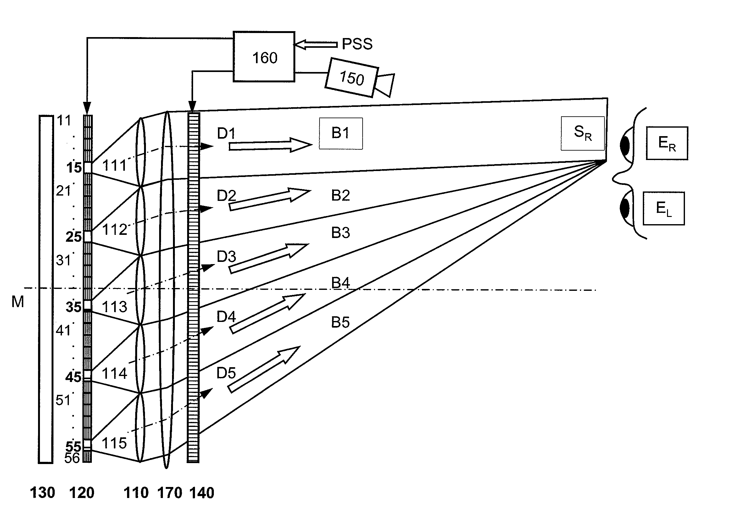
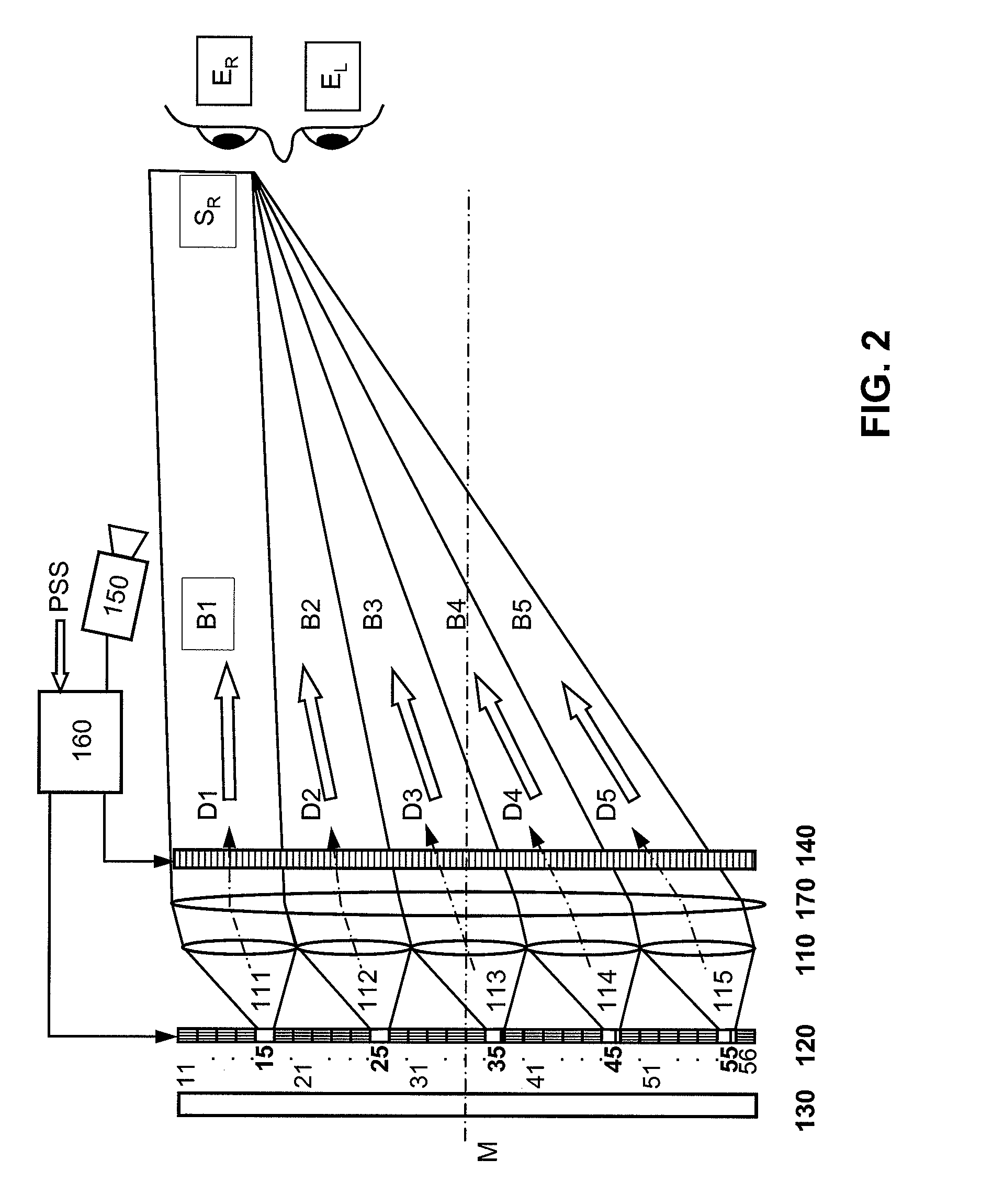
[0050]FIG. 2 shows, with the example of the right eye ER of an observer, the arrangement of elements according to the invention, where numeral 110 denotes an imaging means with lens elements 111-115 and numeral 120 denotes an illumination matrix for generating a bundle of rays B1-B5 for each lens element 111-115. In this embodiment, the illumination matrix 120 is a shutter which uses the light of a large-area light source 130. The shutter contains transmissive illumination elements 11-56. It is an LCD or FLCD panel. In this embodiment, the imaging means 110 is a lenticular. The illumination matrix 120 is disposed about in the focal plane of this lenticular, so that bun...


PUM


Abstract

An autostereoscopic multi-user display comprising a sweet-spot unit which is directionally controlled by a tracking and image control device (160), wherein an illumination matrix (120) is provided with separately activatable illuminating elements (11 . . . 56), in addition to an imaging device used to alternatingly image active illuminating elements, for making expanded sweet spots (SRI/SR2) visible to various eye positions (EL1/ERI, EL2/ER2) of viewers observing alternating images or a stereoscopic image sequence on a transmissive image matrix (140) with the aid of directed beams (B1R . . . B5L). According to the invention, the imaging device comprises an imaging matrix (110) provided with a plurality of lens elements (111 115) whose focal length is small in order to image the active illuminating elements in an enlarged manner onto the sweet spots (SRI/SR2), and a field lens (171), which follows the imaging matrix (110), in order to keep the distances of the activated illuminating elements between adjacent beams (B1, B2,B4, B5) as constant as possible and in order to assist selection of the directions (D1. . . D5) with the illumination matrix (120) for the beams.

Description

[0001] The present invention relates to an autostereoscopic multi-user display having a sweet-spot unit for focussing light to form bundles of rays directed towards the eyes of one or multiple observers, and an image display matrix for alternate modulation of the light of the sweet-spot unit with two-dimensional images with monoscopic or stereoscopic image sequences. In this document, the term “multi-user display” designates a device which can be used by multiple observers for viewing alternate images of image sequences in the form of 3D scenes simultaneously and independently. The present invention takes advantage of temporal interleaving of single images for each of the observers' eyes. When employing this representation method, the resolution is maintained and is not reduced by a factor that represents the number of perspectives, as would be the case with spatial interleaving methods. The resolution is the same as the resolution of the image display matrix. [0002] The auto stereo...

Claims


Application Information

Patent Timeline
IPC IPC(8): G02F1/1335G02B27/22H04N13/00
CPCG02B27/225H04N13/0404H04N13/0418H04N13/0477H04N13/047H04N13/305H04N13/32H04N13/376H04N13/368G02B30/28G02B27/0093H04N13/00
Inventor SCHWERDTNER, ARMIN
Owner SEEREAL TECHNOLOGIES
Why Eureka
Try Eureka