Methods for coating curved surfaces with a polarizing liquid

a technology of polarizing liquid and curved surfaces, applied in the field of coating lenses, can solve the problems of increased cost, difficult to change, film-based products suffer from certain performance/technology shortcomings, etc., and achieve the effect of short tim

Active Publication Date: 2007-08-16
ESSILOR INT CIE GEN DOPTIQUE
View PDF13 Cites 20 Cited by
  • Summary
  • Abstract
  • Description
  • Claims
  • Application Information

AI Technical Summary

Benefits of technology

[0013] The inventors have developed manners in which to apply polarizing liquids to curved surfaces, including those that have not previously been treated to create an orientation for the polarized coating, and thereafter form polarized coatings. A major benefit afforded by the present methods is that polarized coatings may now be created on made-to-order prescription lenses (e.g., ophthalmic lenses) in a short amount of time. As a result, custom lens makers may now create polarized coatings for their customers on demand, without needing to retain a separate inventory of polarized products.

Problems solved by technology

The final optical properties of the resulting lens are determined by the film and are not easily altered.
Additionally, film-based lenses require a separate inventory of polarized products, which can lead to increased costs.
Film-based products suffer from certain performance / technology shortcomings.
For example, if the polarization axis is not placed within three (3) degrees of the optic axis of a progress lens, the product is not acceptable.
Also, a film placed on a progressive lens can greatly limit the final thickness of a wearer's lens due to the film's thickness.
Furthermore, the precursor film to the polarization film can have cosmetic impurities / non-uniformities due to the nature of dying the polarization film (also known in the art as stretch films).
Such non-uniformity, which can be observed as streaking in the film's coloration, can be exacerbated by the casting process, during which a thermal or chemical attack of the film can lead to dye bleach or further color non-uniformity.
Such a process, commercially, is “dirty” and not readily adaptable or necessarily compatible with all lens materials and curvatures.
The scratching is also likely to induce some haze in the final product.
The patent also does not suggest utilizing shear flow alone in coating a surface with a polarizing liquid.
They are not suited to use on non-flat surfaces.

Method used


Image

  • Methods for coating curved surfaces with a polarizing liquid
  • Methods for coating curved surfaces with a polarizing liquid
  • Methods for coating curved surfaces with a polarizing liquid

Examples


example 1

[0102] (Materials and Methods)

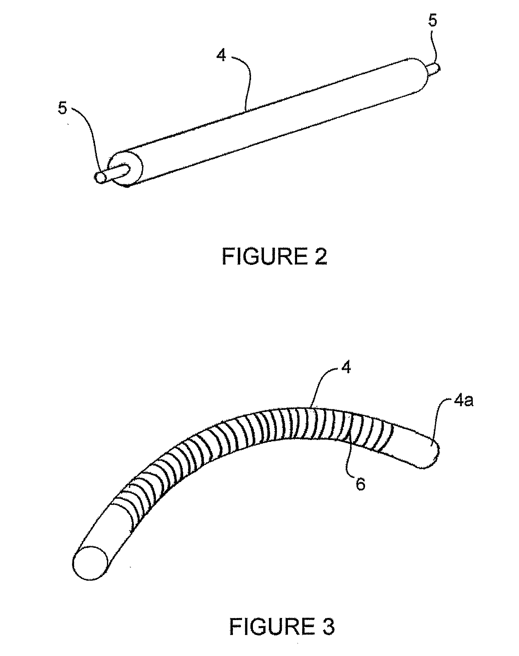
[0103] Flexible Apparatus: In one embodiment of the invention, the flexible apparatus 4 can be made from plastic tubing material. Typical flexible apparatuses had a length of 170 mm of which 105 mm is wrapped with the wire 6. The tubing was wrapped with 100 micron diameter stainless steel Cobra cut Ø0, 10 mm wire from AGIECUT. The plastic tubing can be hard vacuum tubing or flexible “Tygon” tubing. The Tygon tubing used in this experiment had an overall diameter of 7 mm with a wall thickness of 1 mm. In preferred embodiments, the tubing was clear flexible tubing (tubing polyvinyl ¼OD× 3 / 16ID Parker #PV403-1).

[0104] Lens Holder: The lens holder 12 used was a 6 base aluminized hollow half-sphere. The crown of the sphere was remove so that a 6-base piano ORMA® lens would form a smooth “flush” curve.

[0105] Dye application: To permit complete coverage of the lens, the lens was placed in a holder that had a curvature to match the radius of curvature of the...

example 2

[0106]

(Results)ALIGNMENTSAMPLEDYE*METHODCONTRAST RATIO1TCF N°15.05.115Flexible rod30.64from Optiva2TCF N°15.05.115Flexible rod36.08from Optiva3TCF N°15.05.115Flexible rod25.06from Optiva4TCF N°15.05.115Flexible rod44.63from Optiva5TCF N°15.05.115Flexible rod36.99from Optiva6TCF N°15.05.115Flexible rod63.81Mechanical gradefrom Optiva7TCF N°15.05.115Flexible rod71.44Mechanical gradefrom Optiva8TCF N°15.05.115Flexible rod72.24Mechanical gradefrom Optiva9TCF N°15.05.115Flexible rod51.62Mechanical gradefrom Optiva10TCF N°15.05.115Flexible rod66.65Mechanical gradefrom Optiva

TCF N°15.05.115 and TCF N°15.05.115 Mechanical grade are dye solutions (11.5%) of 3 dyes in water.

[0107] The contrast ratio is the ratio of luminous transmittance between parallel and perpendicular positions. The transmission measurements were performed on a Lamda 900 spectrometer in a spectral range of 380-780 nm using a reference polarizer in the beam path. The photopic response was calculated based upon the full sp...


PUM

PropertyMeasurementUnit
diameteraaaaaaaaaa
lengthaaaaaaaaaa
diameteraaaaaaaaaa

Abstract

Methods and apparatuses for coating at least a portion of a curved surface of a lens with a polarizing liquid are disclosed throughout the specification. For example, there is provided a method comprising providing a lens having a curved surface, and applying a polarizing liquid to at least a portion of the curved surface by shear flow with a flexible apparatus. Other methods are included. Apparatuses include ophthalmic lenses having polarized coatings formed according to any of the disclosed methods.

Description

BACKGROUND OF THE INVENTION [0001] A. Field of the Invention [0002] The invention relates generally to methods of coating lenses. More particularly, the invention relates to methods of applying polarized coatings to curved lenses. [0003] B. Description of Related Art [0004] Polarized lenses block light of certain polarization states. By blocking horizontally polarized light, a polarized lens reduces glare that would otherwise exist through a non-polarized lens, such as glare off water, roads, and other objects. As a result of the reduced glare, objects become more distinct and true colors more clear. There are currently several different known systems for polarizing lenses for use in eyewear. [0005] 1. Film-based Polarizing Systems [0006] Certain of today's current eyewear products are fabricated by casting polyvinylalcohol-iodine films into a thermoset lens or by insert injection molding of a laminated polarized film to a thermoplastic lens. From a business perspective, these techn...

Claims


Application Information

Patent Timeline
Patent Type & Authority Applications(United States)
IPC IPC(8): G02C7/02B29D11/00B05C11/02B05C11/04B05D1/40B05D5/06G02B1/10G02B5/30
CPCB05C11/025B05C11/041Y10S425/808G02B1/10G02B5/3016B29D11/00865B29D11/00009
Inventor MOSSE, HERBERTMUISENER, RICHARD
Owner ESSILOR INT CIE GEN DOPTIQUE
Why Eureka
Try Eureka