Signal transmitting method (variants) and device for carrying out said method

a signal transmitting and variable technology, applied in the field of radio engineering, can solve the problems of limiting the downlink capacity, fading and interference, and requiring more complicated and expensive transmitters and receivers, so as to reduce increase the number of diversity channels, and increase the efficiency of fading averaging

Inactive Publication Date: 2007-08-16
JSC KODOFON
View PDF7 Cites 14 Cited by
  • Summary
  • Abstract
  • Description
  • Claims
  • Application Information

AI Technical Summary

Benefits of technology

[0143] The present invention provides a method (embodiments) and apparatus (embodiments) for data transmission used to increase the efficiency of information signal transmission in downlink and, hence, maximize the information signal reception quality at the mobile station as well as to reduce the feedback channel load.

Problems solved by technology

However, the use of advanced transmission and reception methods requires more complicated and expensive transmitters and receivers.
The key factors limiting the downlink capacity are fading and interference.
The rest of transmitted energy acts as interference for other mobile stations.
First, it does not use the efficient transmit diversity method, that is, coherent transmit diversity.
Moreover, it uses one adaptive antenna array, which reduces the degree of diversity, compared to when several adaptive antenna arrays are used.
When the information signal copies transmitted from the adaptive antenna arrays are subject to frequency-selective fading, the described method and apparatus do not allow coherent summation of the information signal copies at the mobile station.
Consequently, the known method and apparatus do not provide the specified advantages of coherent transmit diversity.
Hence, these method and apparatus do not use all available transmission directions and decrease the efficiency of fading averaging.
The weighting coefficients of transmit diversity might not be sufficiently accurate.
As a result, this would decrease the efficiency of the method and apparatus for data transmission.

Method used


Image

  • Signal transmitting method (variants) and device for carrying out said method
  • Signal transmitting method (variants) and device for carrying out said method
  • Signal transmitting method (variants) and device for carrying out said method

Examples


first embodiment

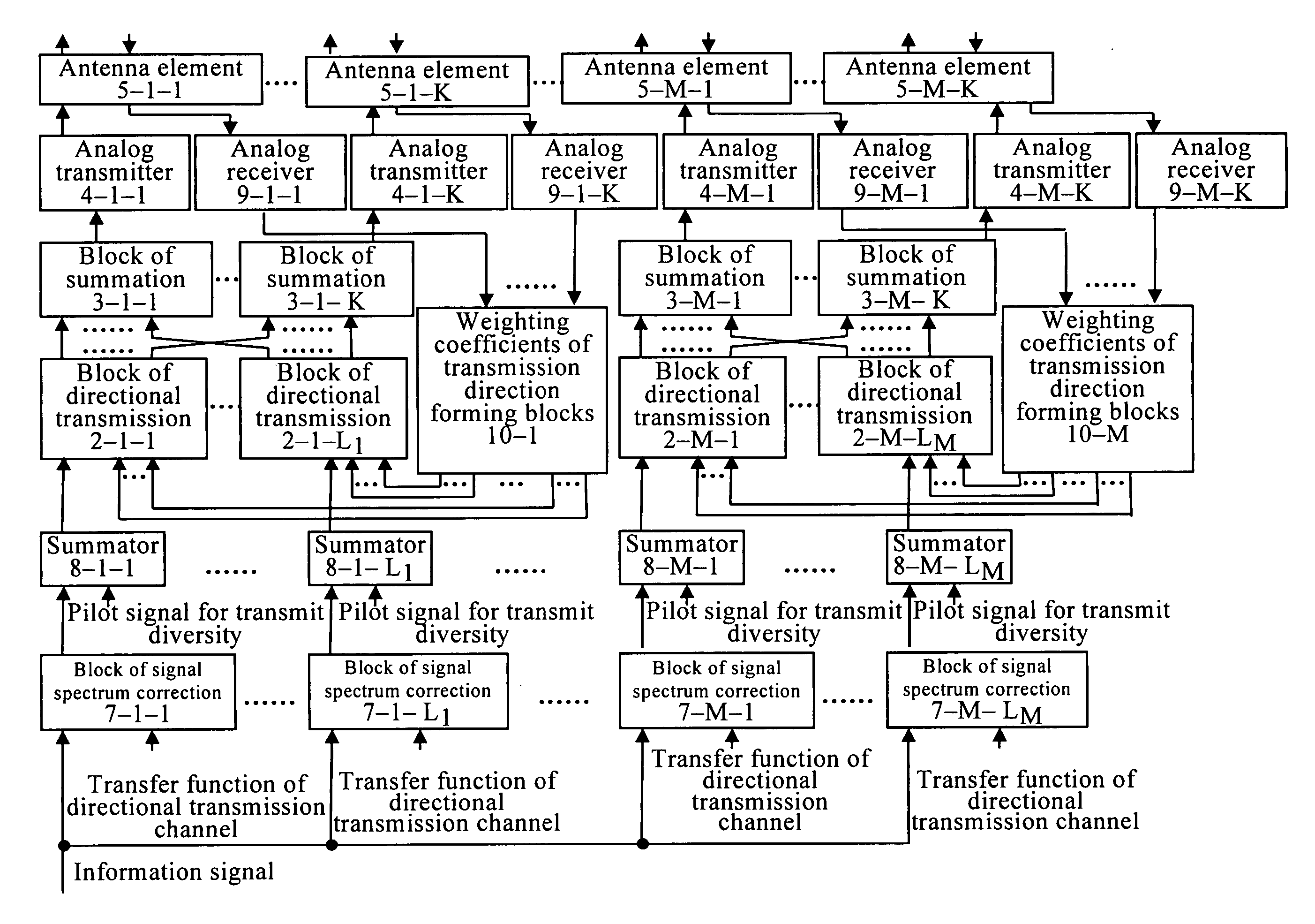
[0210] The method for data transmission is implemented using the apparatus the block-diagram of which is shown in FIG. 9.

[0211] M diverse groups of transmission channels each having K transmission channels, where M≧1, K≧1, are formed at the base station.

Each of M·K transmission channels is formed by the corresponding analog transmitter 4-m-k and the corresponding antenna element 5-m-k, where m takes on the values from 1 to M, and k takes on the values from 1 to K.

[0212] Each of M diverse groups of transmission channels is formed by the corresponding block of directional transmission, one of 2-m-j blocks, where j takes on the values from 1 to Lm, the corresponding analog transmitters 4-m-1-4-m-K and the respective antenna elements 5-m-1-5-m-K.

[0213] Each diverse group of transmission channels is an adaptive antenna array. The total of M adaptive antenna arrays are used for transmission.

[0214] Pilot signals are transmitted from the base station to the mobile station from all M·K...

second embodiment

[0250] The method of data transmission is implemented using the device, whose block-diagram is shown in FIG. 10. M diverse groups of transmission channels each having K transmission channels, where M≧1, K≧1, are formed at the base station.

[0251] Pilot signals are transmitted from the base station to the mobile station from all M·K transmission channels of diverse groups.

[0252] Impulse responses of M·K transmission channels of diverse groups are estimated at mobile station using transmitted pilot signals.

[0253] Lm sets of weighting coefficients of transmission direction each having K-1 weighting coefficients of transmission direction are formed at mobile station using the estimated impulse responses of M·K transmission channels of diverse groups, where 1≦Lm≦K and m=1, 2, . . . , M.

[0254] This operation is performed in the same way as the one according to the first embodiment of data transmission method.

[0255] A feedback signal containing Lm weighting coefficients of transmission...

third embodiment

[0270]FIG. 10 is the block-diagram of the apparatus for data transmission according to the

[0271] M diverse groups of transmission channels each having K transmission channels are formed at the base station, where M≧1, K≧1.

[0272] Pilot signals are transmitted from the base station to the mobile station from all M·K transmission channels of diverse groups.

[0273] Impulse responses of M·K transmission channels of diverse groups are estimated at the mobile station using the transmitted pilot signals.

[0274] Lm sets of weighting coefficients of transmission direction each having K-1 weighting coefficients of transmission direction are formed at the mobile station for each of M diverse groups of transmission channels using the estimated impulse responses of M·K transmission channels of diverse groups, where 1≦Lm≦K and m=1, 2, . . . , M.

[0275] This operation is done in the same way as the one according to the second embodiment of data transmission method.

[0276] Transfer functions of cha...


PUM


Abstract

A group of inventions relate generally to radio engineering, and more particularly to a method of data transmission (embodiments) and apparatus of data transmission (embodiments) to be used, for example, in cellular communications systems when transmitting an information signal over the downlink from base station to mobile station. The goal of the present method of data transmission (embodiments) and the apparatus of data transmission (embodiments) is to increase the efficiency of the information signal transmission in the downlink and, thus, maximize the information signal reception quality at the mobile station. The claimed solution also reduces the feedback channel (from mobile to base station) load. The object of the invention is attained by correcting the spectrum of the transmitted information signal copies, transmitting the information signal copies from each adaptive antenna array in each efficient transmission direction, estimating the transfer functions of the directional transmission channels using the pilot signals transmitted from each antenna element, pilot signals for transmit diversity, transmitted from each adaptive antenna array in each efficient transmission direction, combining these two estimates, and by estimating the efficient transmission directions at the base station using the mobile station signal.

Description

FIELD OF THE INVENTION [0001] The present group of inventions relate generally to radio engineering, and more particularly to a method of data transmission (embodiments) and apparatus of data transmission (embodiments) to be used, for example, in cellular communications systems when transmitting an information signal over the downlink from base station to mobile station. DESCRIPTION OF THE PRIOR ART [0002] Increasing the communication systems capacity by means of efficient transmission and reception methods is currently a promising task. However, the use of advanced transmission and reception methods requires more complicated and expensive transmitters and receivers. In cellular communication systems, it appears reasonable to increase the complexity of a base station without influencing that of a mobile station. Hence, it is important to provide more efficient transmission methods in the downlink (from base station to mobile station) and reception methods in the uplink (from mobile ...

Claims


Application Information

Patent Timeline
Patent Type & Authority Applications(United States)
IPC IPC(8): H04J9/00H04Q7/00H04B1/707H04B7/06H04B7/26
CPCH04B1/7097H04B2201/709709H04B7/0658H04B7/0626H04B7/06H04B7/0619H04L25/0204H04L25/024
Inventor GARMONOV, ALEXANDR VASILIEVICHSAVINKOV, ANDREW YURIEVICHFILIN, STANISLAV ANATOLIEVICH
Owner JSC KODOFON
Why Eureka
Try Eureka