
Conference terminal with echo reduction for a voice conference system

a conference system and conference terminal technology, applied in the field of conference terminals with echo reduction, can solve the problems of no uniform conference signal in these systems, inability to communicate directly with a group of people, and limited radio resources for a radio-based voice conference system, so as to achieve no noise suppression

Active Publication Date: 2007-08-16
FRAUNHOFER GESELLSCHAFT ZUR FOERDERUNG DER ANGEWANDTEN FORSCHUNG EV
View PDF8 Cites 24 Cited by
  • Summary
  • Abstract
  • Description
  • Claims
  • Application Information

AI Technical Summary

Benefits of technology

[0024] It is an object of the present invention to provide a conference terminal with improved echo reduction.

Problems solved by technology

Voice conference systems are used anywhere where communication within a group of persons is not possible in a direct way due to too large distances, too high noise level or due to other reasons.
In a teleconference, delay times occur on the transmission path, which can cause spurious echoes.
However, no uniform conference signal exists in these systems, but every participant obtains a specific conference signal, which does not include his own signal.
However, the radio resources available for a radio-based voice conference system are very limited.
If the voice conference system uses digital radio transmission and digital audio encoding, a delay of the signal in the two-digit millisecond range results on the transmission path.
Further, in contrast to conventional teleconference systems, due to the limited radio resources, it is not possible in wireless voice conference systems that every participant receives a specific conference signal, which does not include his own signal, from the central unit via an exclusive return channel.
Thus, the uniform conference signal has a significant time delay in a two-digit millisecond range compared to the voice signal of a speaker.
This limits currently the applicability of a digital signal transmission in connection with encoding for voice conference systems with delays.
Particular problems occur when the propagation time of a transmitted voice signal from one terminal to another terminal is more than about 20 milliseconds.
During encoding, large delays in a two-digit millisecond range occur.
By digital radio transmission and particularly digital signal processing and encoding and decoding of the digitally transmitted voice signal, a significant delay of the signal in the two-digit millisecond range results on the transmission paths.
Thereby, in the case of digital encoded audio signal transmission, a significant delay in the two-digit millisecond range results.
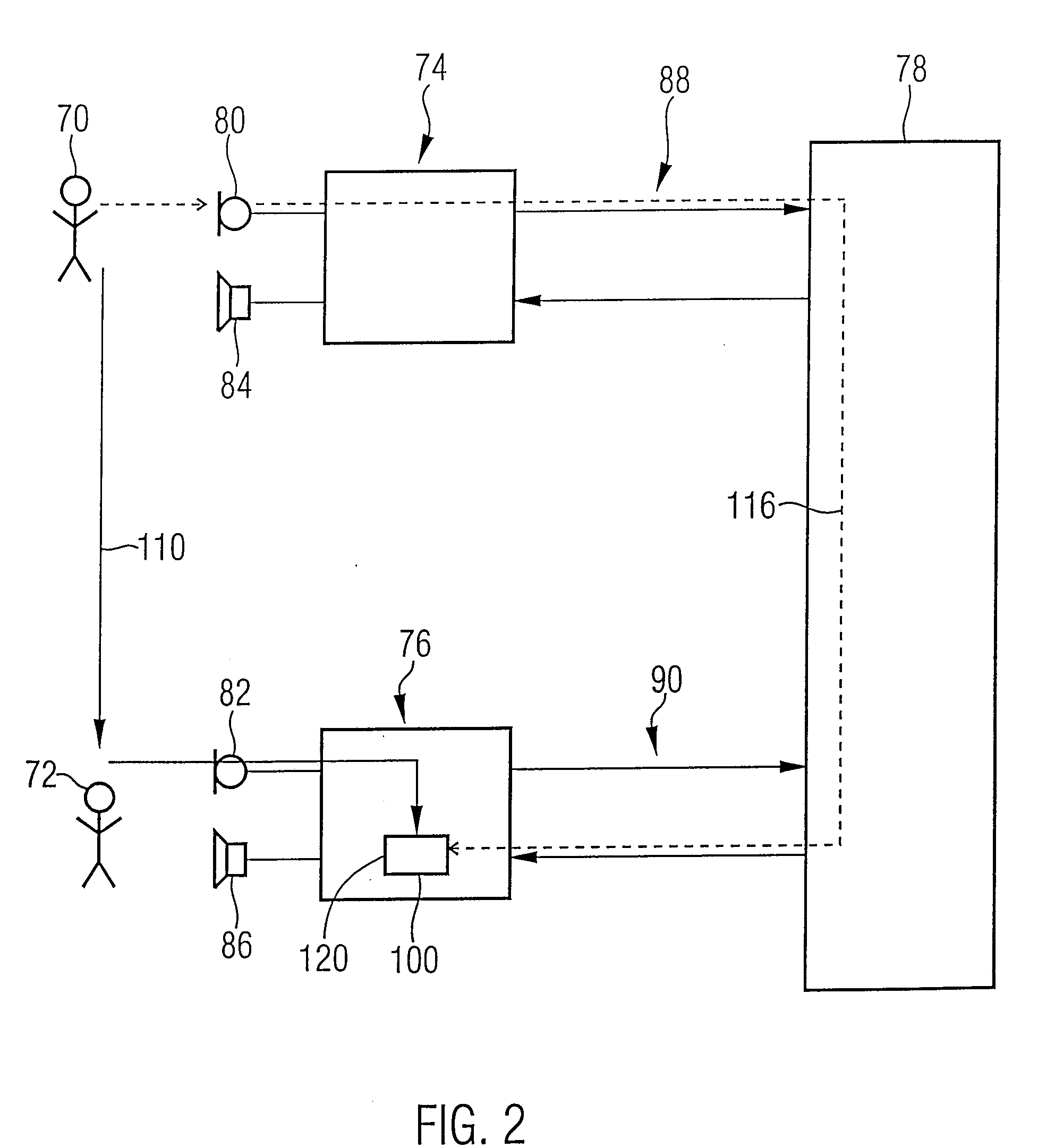
If the second conference participant hears the voice contribution of another participant both on the direct acoustic path and with time delay via the voice conference system, this is also perceived as spurious echo.
Further, it has to be noted that the different types of echoes need to be counteracted with different degrees of difficulty.
A remote own echo, which results due to the fact that the own conference terminal receives his own voice signal, passes the same on to the central unit and receives it again from there, cannot be easily suppressed.
However, a digital encoded voice signal transmission, where delays occur inevitably, is made more difficult or even impossible by the echo.
The suppression of an echo is more problematic when the propagation time of the signal or the difference of the propagation times, respectively, on two different transmission paths is not known.
In this case, echo suppression is very difficult to accomplish and is thus not performed in voice conference systems according to the prior art.
However, such a measure is not satisfying, since it does not correspond to the natural way of expression of the speakers.
Thus, it is very awkward for the speaker to use a conventional voice conference system, particularly when neighboring conference participants are very close to each other.

Method used


Image

  • Conference terminal with echo reduction for a voice conference system
  • Conference terminal with echo reduction for a voice conference system
  • Conference terminal with echo reduction for a voice conference system

Examples


Embodiment Construction

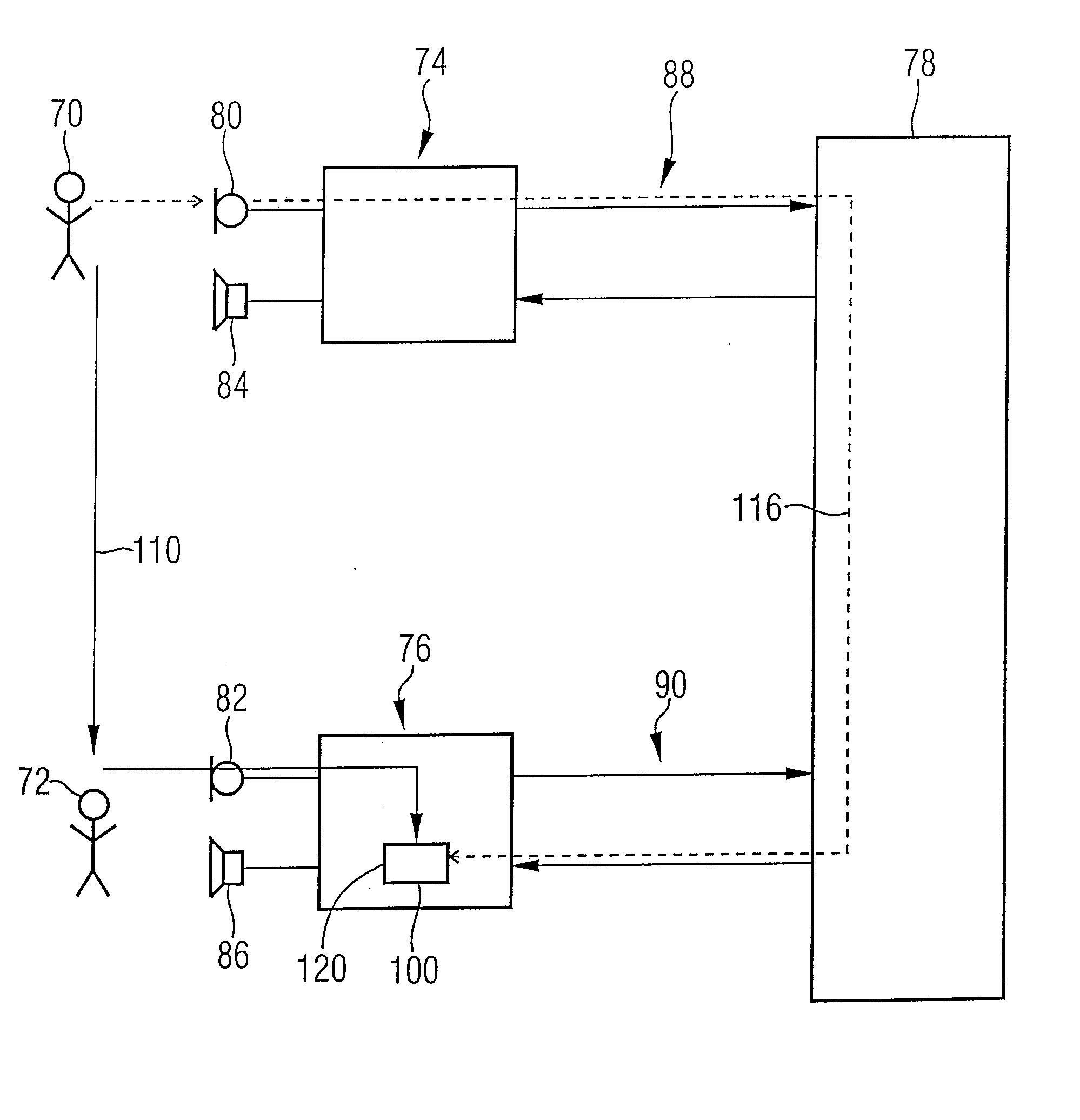
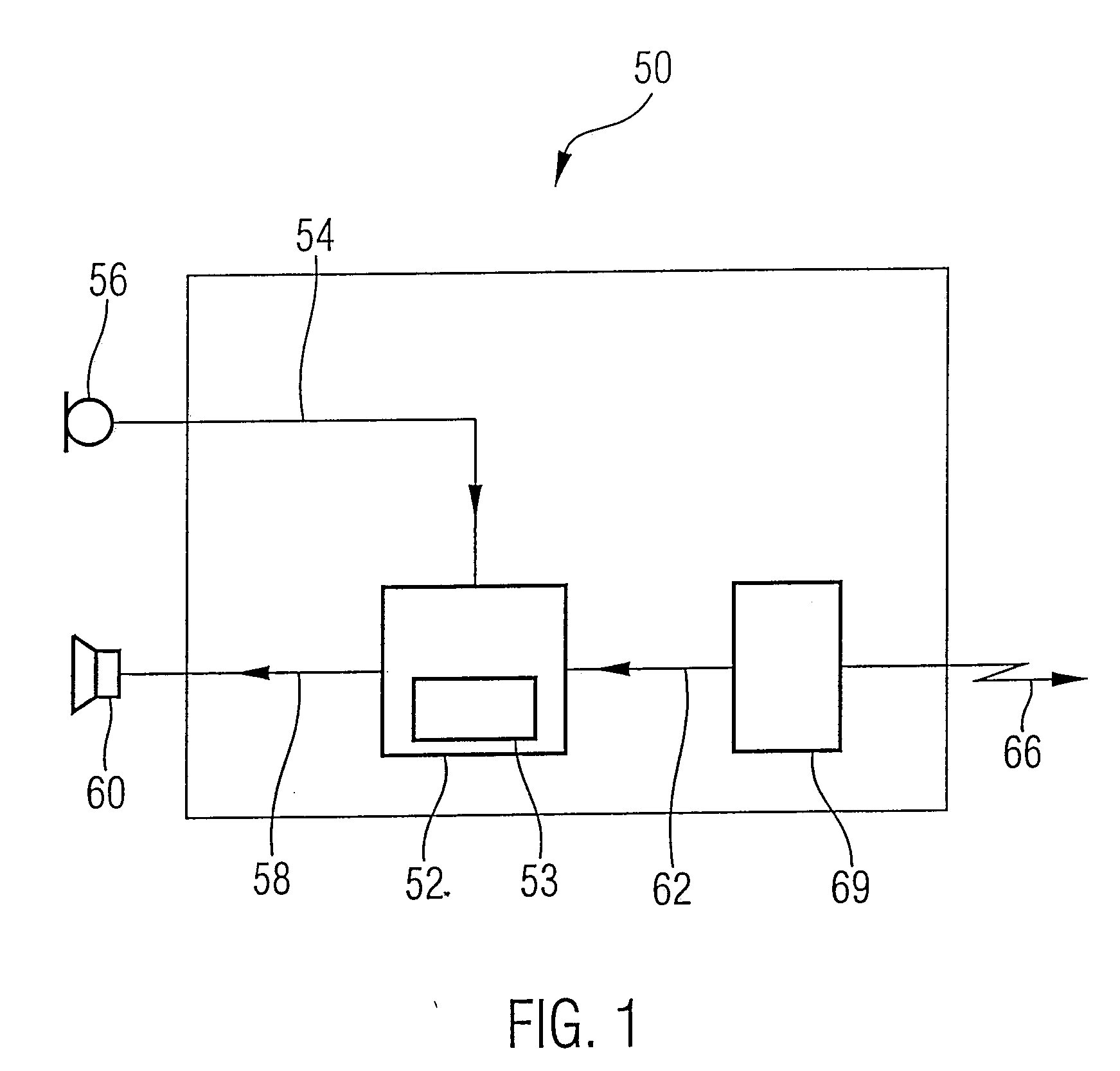
[0046]FIG. 1 shows a block diagram of an inventive conference terminal according to an embodiment of the present invention. The conference terminal is designated by 50 in its entirety. Core of the conference terminal 50 is a means 52 for echo suppression, which comprises a means 53 for noise suppression. The means 52 for echo suppression receives a microphone signal 54 from a first sound transducer means 56 and provides a loudspeaker signal 58 to a second sound transducer means 60. Further, a composite conference signal 62 is supplied to the means 52 for echo suppression, which a connecting means 64 receives from a central unit. The transmission path between the central unit and the connecting means 64 is here designated by 66.

[0047] The first sound transducer means 56, which is preferably implemented as microphone, generates a microphone signal 54 from an incident acoustic signal. The second sound transducer means 60, which is preferably implemented as loudspeaker, generates an ac...


PUM


Abstract

A conference terminal for a digital voice conference system comprises a first sound transducer means, which is implemented to generate a microphone signal from an acoustic signal, a second sound transducer means, which is implemented to generate an acoustic signal from a loudspeaker signal, a connecting means, which is implemented to enable a connection between conference terminal and a conference central unit, to receive a composite conference signal from the conference central unit, and a means for echo suppression, which is implemented to combine the microphone signal or a signal derived therefrom in a noise suppression means with a composite conference signal in a listening operation of the conference terminal, such that a loudspeaker signal results, in which the acoustic signal, on which the microphone signal is based, is reduced. Such a conference terminal allows the suppression of a remote own echo and a remote foreign echo, whereby digital wireless voice conference systems can be realized, which ensure high voice quality and noise immunity with minimum wiring effort.

Description

CROSS-REFERENCE TO RELATED APPLICATION [0001] This application is a continuation of copending International Application No. PCT / EP2005 / 007498, filed Jul. 11, 2005, which designated the United States and was not published in English.BACKGROUND OF THE INVENTION [0002] 1. Field of the Invention [0003] The present invention relates generally to a conference terminal for a voice conference system, particularly to a conference terminal with echo reduction for a digital voice conference system. [0004] 2. Description of the Related Art [0005] Voice conference systems are used anywhere where communication within a group of persons is not possible in a direct way due to too large distances, too high noise level or due to other reasons. Here, it has to be differentiated between systems where the communicating persons are very far apart from each other, so that direct acoustic coupling between the persons is not given, and they can only hear the other conference participants via the voice confe...

Claims


Application Information

Patent Timeline
Patent Type & Authority Applications(United States)
IPC IPC(8): H04M9/08
CPCH04M9/082H04M3/568H04M3/56H04M3/002
Inventor TITTLE, MARTINLUTZKY, MANFREDHUPP, JUERGEN
Owner FRAUNHOFER GESELLSCHAFT ZUR FOERDERUNG DER ANGEWANDTEN FORSCHUNG EV
Learn More