Visual prosthesis

a prosthetic device and visual technology, applied in the field of visual prosthetic devices, can solve the problems of diseased retinas being effectively bypassed, the effect of reducing the overall efficiency of the electrode array, avoiding the stimulation of the same optic nerve fiber, and increasing the resolution of vision

Inactive Publication Date: 2007-08-16
REN QIUSHI
View PDF11 Cites 31 Cited by
  • Summary
  • Abstract
  • Description
  • Claims
  • Application Information

AI Technical Summary

Benefits of technology

[0014] In another embodiment of the stimulating electrode array, a parylene or polymer based, paper-like material can be used as a base member for an electrode array. The thickness of such base members is in a range between 1 micron to 2 millimeters (1 μm-2 mm). In this embodiment, the geometrical arrangement of the probes on each base member of the electrode array is stair-like, with each probe preferably having a length that is in a range between five hundred microns and five millimeters (500 μm-5 mm). Also, the probes can be spaced both horizontally and vertically from adjacent probes on the same base member by a distance that is in a range between ten microns and five millimeters (10 μm-5 mm). Specifically, such an arrangement is provided in order to avoid stimulating the same optic nerve fiber or fibers by different probes, and thereby reducing the overall efficiency of the electrode array.
[0015] Two different methods are envisioned for inserting an electrical electrode array into its operational position. In one (i.e. the paper-like array), the optic nerve will first be dissected to create an opening along the axis of the optic nerve. The paper-like stimulating electrode array will then be inserted into the opening with the cable sitting outside the optic nerve for connection to the stimulating unit. In this manner, a plurality of such electrode arrays can be inserted around the optic nerve of the patient to increase the resolution of the vision. In another (i.e. the pin-like electrode), a plurality of pin-like arrays are pushed into the optic nerve. The pin-like array penetrates into the optical nerve and each electrode on each pin will contact fibers of the optical nerve.

Problems solved by technology

Of particular interest here is the situation wherein the retina alone becomes essentially ineffective and unusable for its intended purpose.
These examples, however, rely on a direct electrical stimulation of the retina, and do not suggest how a diseased retina can be effectively bypassed, and still generate a visual sensation for the patient.

Method used


Image

  • Visual prosthesis
  • Visual prosthesis
  • Visual prosthesis

Examples


Embodiment Construction

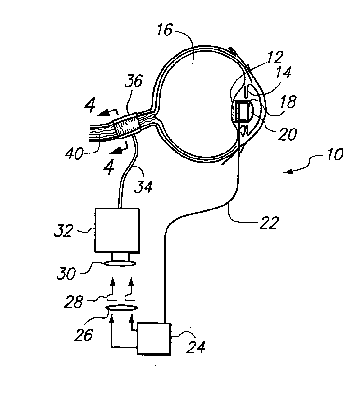
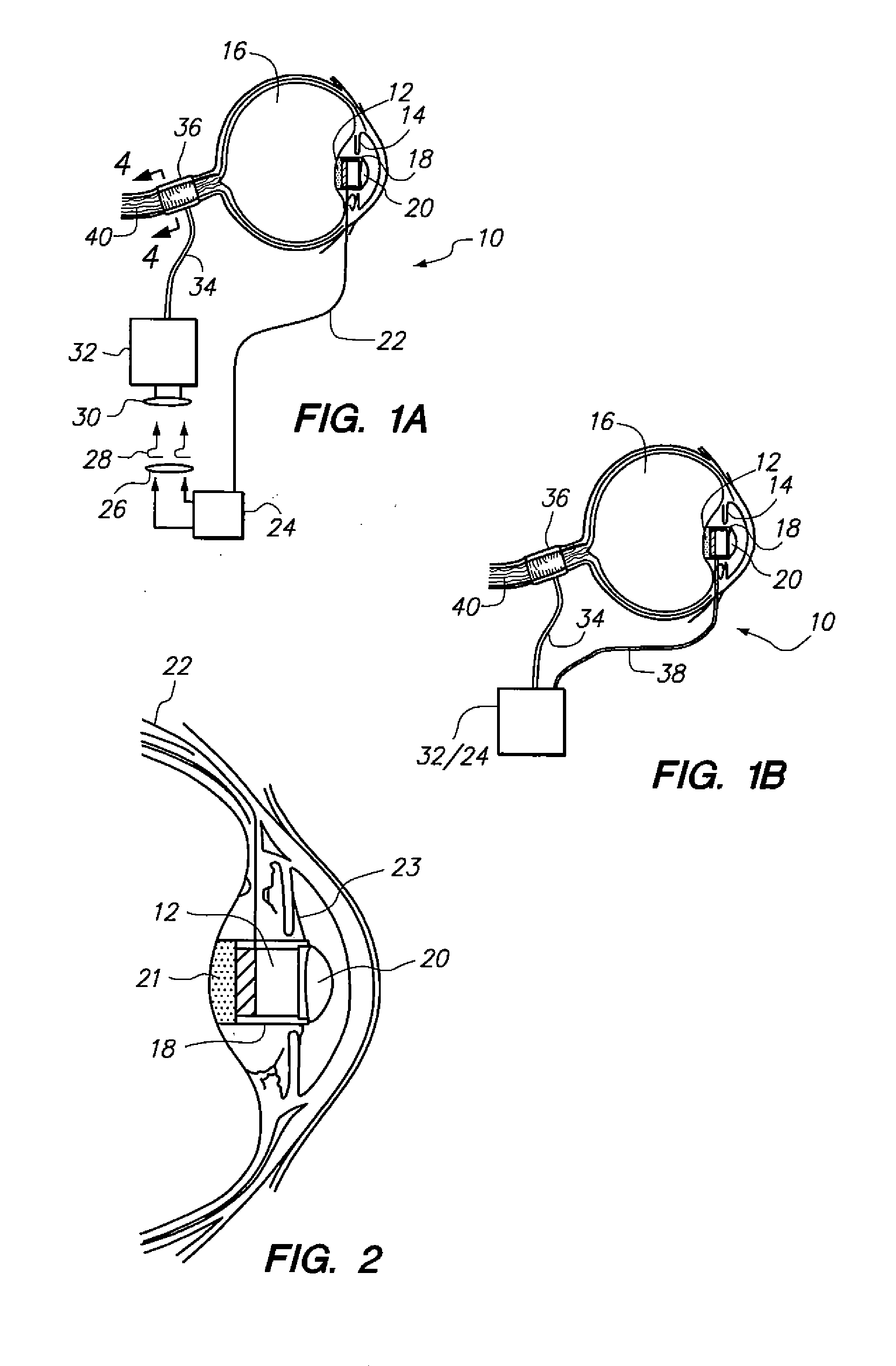
[0030] Referring initially to FIG. 1A, a visual prosthesis in accordance with the present invention is shown and is generally designated 10. As shown, the prosthesis 10 includes an intraocular (CMOS) camera 12 that is mounted on the lens 14 in an eye 16 of a patient. Further, as also shown in FIG. 1A, the camera 12 is mounted in a chamber 18 along with a wide angle lens 20. Together, the chamber 18 and lens 20 provide a hermetic seal for the camera 12. Preferably, the camera 12 is a CMOS camera having a sensor area 3.37 mm×2.54 mm, with pixel sizes of 2.0 μm×2.0 μm and an output of 25 frames per second at 128×128 pixel resolution. Other, similar type cameras with different pixel size and resolution, however, could be used as well. As envisioned for the present invention, the various types of CMOS cameras that can be used as the camera 12 will vary primarily in the type of power supply that is used. Referring now to FIG. 2 it will be seen that the camera 12 typically includes a power...


PUM


Abstract

A prosthesis for viewing an object includes a CMOS camera that is mounted on an eye lens of a patient to create a visual image. A process controller then creates an encoded signal of the visual image that has specific intensity and position information for respective pixels. Next, this encoded signal is transmitted to a stimulating unit implanted in the cranium, where it is decoded to create an electrical stimulation signal in accordance with a predetermined data protocol. The electrical stimulation signal is then passed to an electrode array that is coupled to an optic nerve of the patient, to thereby generate phosphenes in the brain for a sensation of visual perception of the object.

Description

FIELD OF THE INVENTION [0001] The present invention pertains generally to visual prosthetic devices for blind persons and to the related surgical technique for implanting the device. More particularly, the present invention pertains to devices and methods for stimulating nerve fibers in the optic nerve to generate phosphenes for a sensation of visual perception. The present invention is particularly, but not exclusively, useful as a device that electronically bypasses the retina to generate a visual image of an object, and then uses image-based signals to directly stimulate nerve fibers in the optic nerve. BACKGROUND OF THE INVENTION [0002] With a normal eye, the visual perception of an object results when light is anatomically converted into impulse signals that will neurologically stimulate the brain. In overview, this conversion essentially involves three separate, but interrelated, functions. First, light from whatever is being viewed needs to be focused in order to create an im...

Claims


Application Information

Patent Timeline
Patent Type & Authority Applications(United States)
IPC IPC(8): A61N1/05A61F9/00
CPCA61N1/36046A61F9/08
Inventor REN, QIUSHI
Owner REN QIUSHI
Why Eureka
Try Eureka