Aerodynamic roof lift-prevention device

Inactive Publication Date: 2007-08-23
VANDENBERG CHARLES J
View PDF55 Cites 19 Cited by
  • Summary
  • Abstract
  • Description
  • Claims
  • Application Information

AI Technical Summary

Benefits of technology

[0004]The system of the present invention addresses this need by providing a turbulence creating device which is mounted to a roof in sufficient number and spaced such that high winds flowing across the roof are caused to become turbulent, th

Problems solved by technology

In areas where high winds can occur, wind damage to roofs, and particularly flat roofs or shallow pitched roofs, can be significant.
The laminar flow of high velocity winds across the surface of a flat roof generates lift which frequently results in detachment of roofing material, particularly where large sheets of material are joined along seams and only adhesively attached to the underlying roof support members at spaced locations.
The lift caused by high winds across the surface of a roof initially tends to lift the roofing fabric or covering from the edges of the roof, followed by the tearing and removal of the entire roof covering, and subsequently the underlying roof str

Method used


Image

  • Aerodynamic roof lift-prevention device
  • Aerodynamic roof lift-prevention device
  • Aerodynamic roof lift-prevention device

Examples


Embodiment Construction

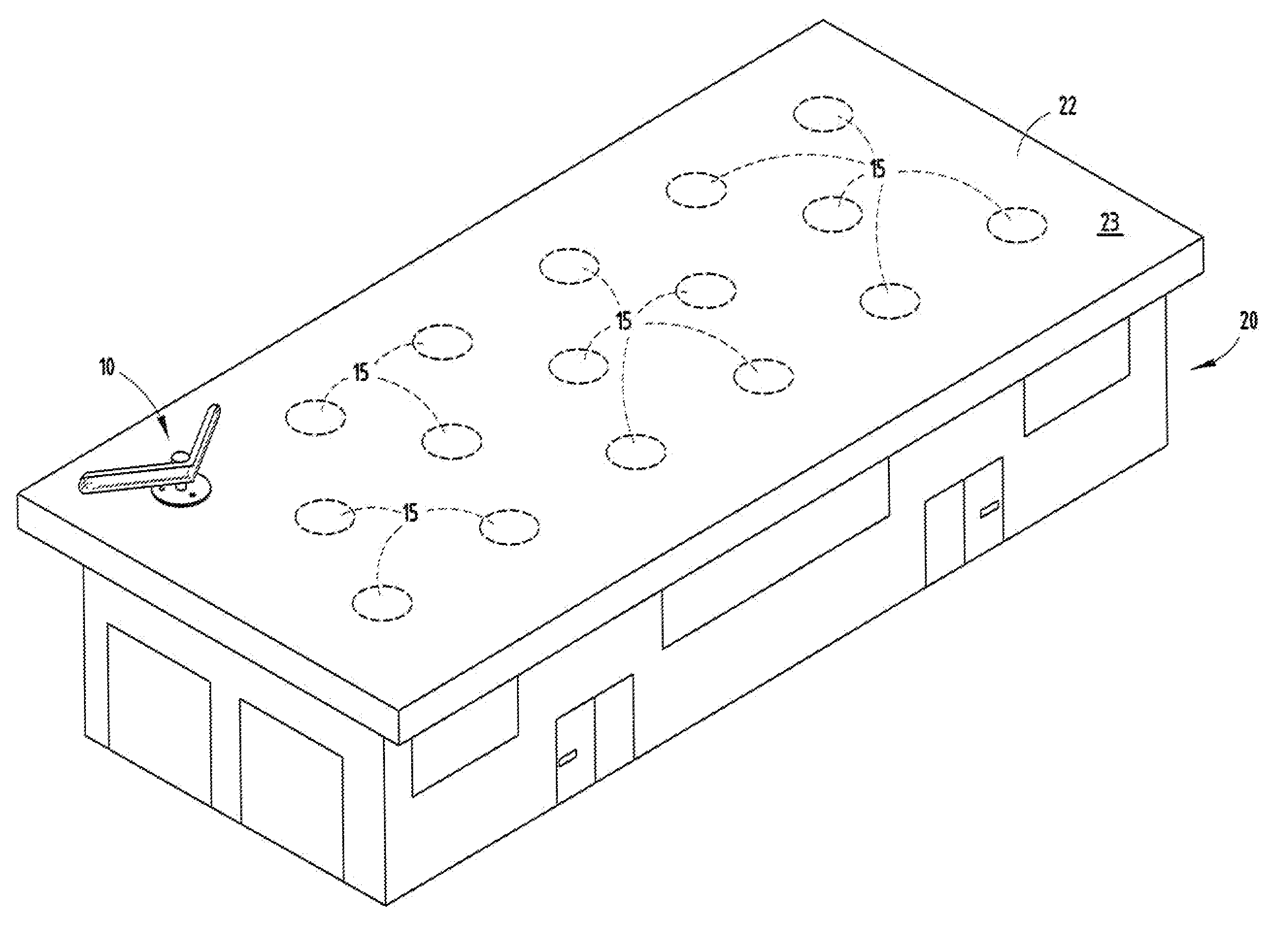
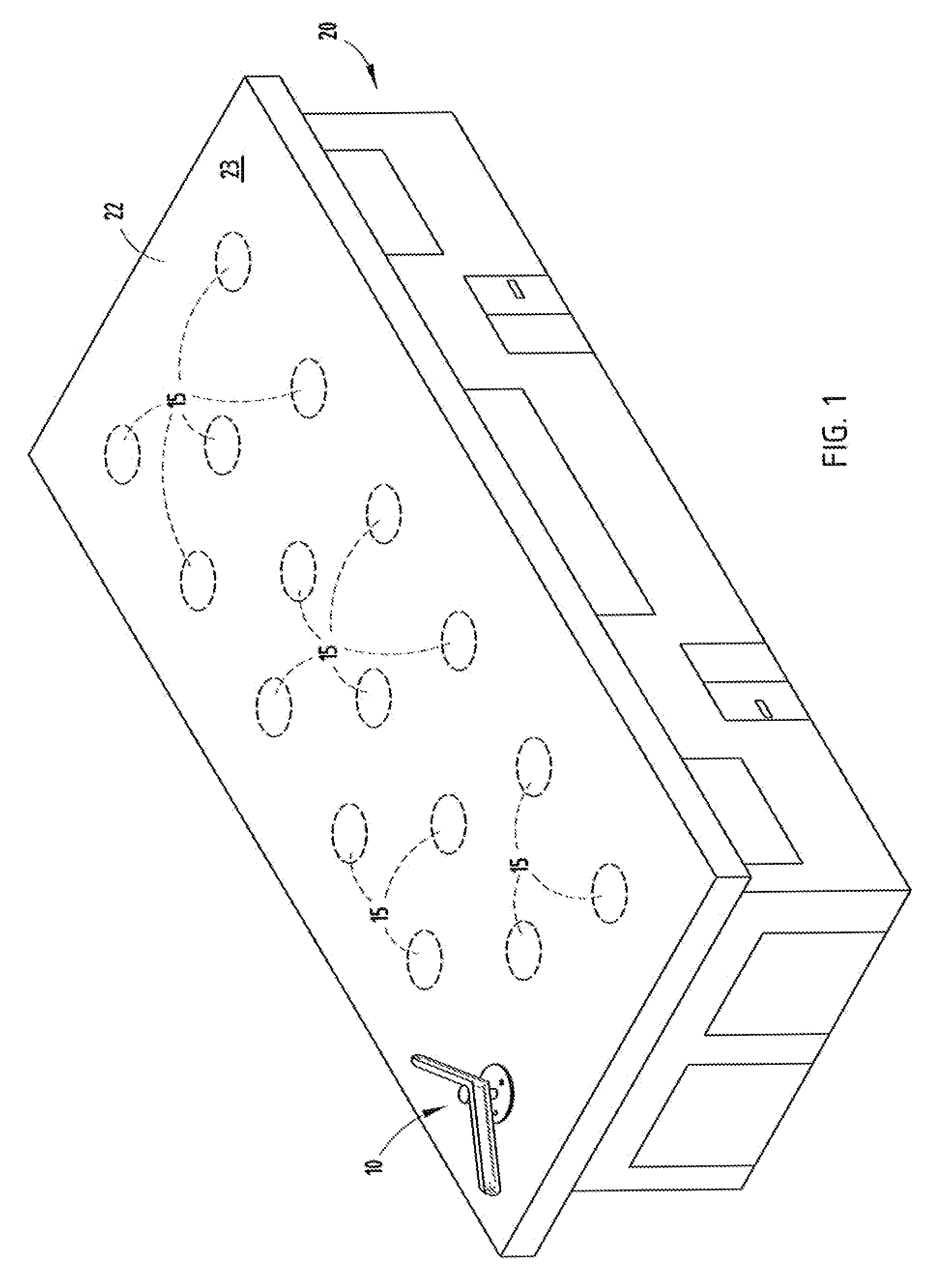
[0027]The spoilers of the invention can be employed for either flat roofs 22 or slightly pitched roofs of a building 20 (FIG. 1) to disturb high velocity laminar airflow which would otherwise reduce the air pressure at the surface of the roof causing lift, which could tear the roof from the building. The surface 23 of roof 22 is typically comprised of a covering sheet of water-impervious material, such as tar paper, PVC, or other sheet material, which comprise individual strips joined at seams by seals and adhesively attached to the underlying roof support sheeting. The roof support sheeting is frequently made of plywood or chipboard sheets. Often surface 23 will include small pea-sized stones, such as pea gravel, to assist in holding the water-impervious material to the underlying structure. Nonetheless, under high wind conditions encountered during wind storms, such as sheer winds, and hurricanes, the surface material 23 frequently lifts off the roof and, in many cases, takes the ...


PUM


Abstract

A turbulence-creating device is mounted to the roof, such that high winds flowing across the roof are caused to become turbulent, thereby interfering with the laminar flow and lift which would otherwise be created. The turbulence-creating devices comprise generally V-shaped or curved spoilers, many of which are pivotally mounted to a vertical mast attached to the roof such that the spoilers face in the direction of the oncoming wind and are shaped to disturb the laminar flow, thereby preventing lift from being generated. In some embodiments, fixed omnidirectional spoilers with curved sides are provided.

Description

CROSS-REFERENCE TO RELATED APPLICATIONS[0001]This application claims priority under 35 U.S.C. § 119(e) on U.S. Provisional Application No. 60 / 764,193 entitled AERODYNAMIC ROOF LIFT-PREVENTION DEVICE, filed on Feb. 1, 2006, by Charles J. VendenBerg, the entire disclosure of which is incorporated herein by reference.BACKGROUND OF THE INVENTION[0002]The present invention relates to a system and method to prevent wind damage to roofs. In areas where high winds can occur, wind damage to roofs, and particularly flat roofs or shallow pitched roofs, can be significant. The laminar flow of high velocity winds across the surface of a flat roof generates lift which frequently results in detachment of roofing material, particularly where large sheets of material are joined along seams and only adhesively attached to the underlying roof support members at spaced locations. The lift caused by high winds across the surface of a roof initially tends to lift the roofing fabric or covering from the e...

Claims


Application Information

Patent Timeline
IPC IPC(8): E04B7/00
CPCE04D13/00
Inventor VANDENBERG, CHARLES J.
Owner VANDENBERG CHARLES J
Why Eureka
Try Eureka