

Work area setting and managing system
a management system and work area technology, applied in soil-shifting machines/dredgers, static indicating devices, instruments, etc., can solve the problems of poor work efficiency, over-the-counter work management devices, and high cost of setting up a management office etc., and achieve low cost, high flexibility and general applicability.
- Summary
- Abstract
- Description
- Claims
- Application Information
AI Technical Summary
Benefits of technology
Problems solved by technology
Method used
Image

Examples
Embodiment Construction
[0023] Below, preferable embodiments of the present invention will be explained with reference to the drawings.
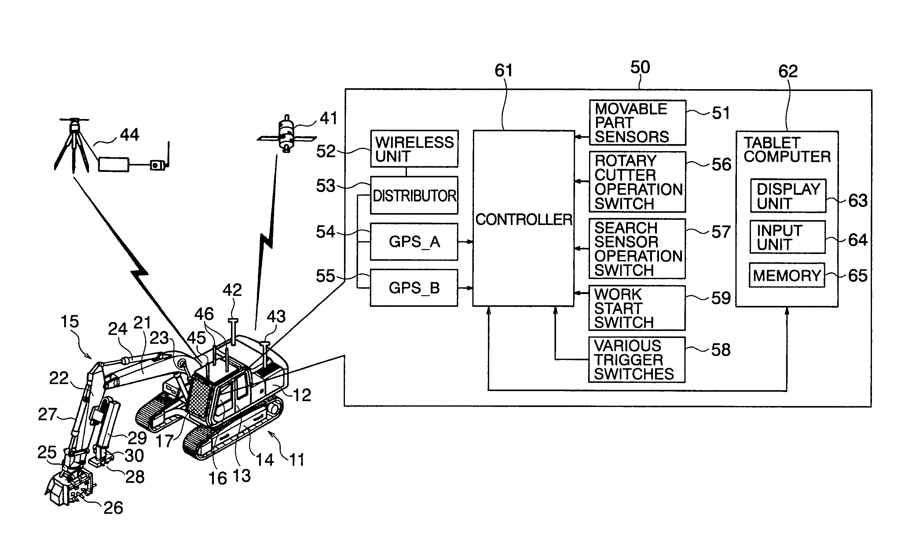
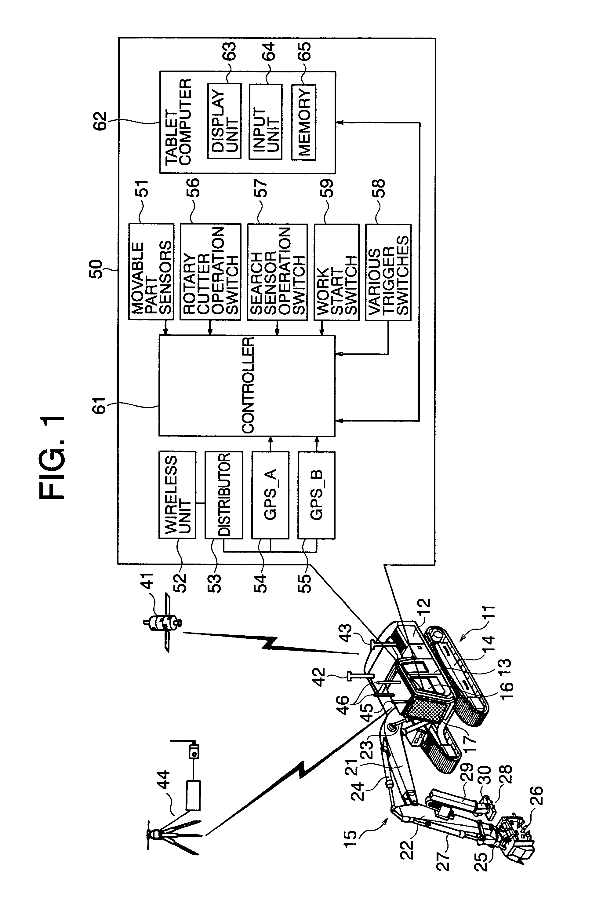
[0024]FIG. 1 is a perspective view of a mobile work machine (land mine disposer) used in the present invention and a block diagram showing the configuration of an electronic system provided in the mobile work machine.
[0025] In the present embodiment, a mobile work machine 11 is typically formed as a land mine disposer. In the following explanation, therefore the mobile work machine 11 is explained as a “land mine disposer 11”. The land mine disposer 11 is comprised of crawler type hydraulic excavator known as a hydraulic construction machine as a base machine. The land mine disposer 11 is provided with a turret 12, operator's compartment 13, chassis 14, and front attachment 15. The turret 12 is provided on the chassis 14 to be able to turn. The operator's compartment 13 is provided at the front left side of the turret 12. The chassis 14 is a crawler type, but may also be ...
PUM
 Abstract
Description
Claims
Application Information