Subjective Refraction Method and Device for Correcting Low and Higher Order Aberrations

a refraction method and high-order technology, applied in the field of subjective refraction methods, can solve the problems of reducing affecting the accuracy of the refraction method, so as to reduce the long dimension of the linear image, minimize hoa, and eliminate the drawbacks of click-and-measure

Active Publication Date: 2007-08-23
LAI SHUI T
View PDF83 Cites 46 Cited by
  • Summary
  • Abstract
  • Description
  • Claims
  • Application Information

AI Technical Summary

Benefits of technology

[0013] With most auto-refractor or wavefront aberrometers, the measurement that determines the patient's refraction errors is taken with a single click. That is, the measurement is objective, with no participation of the patient's image perception formation process from the retina to the brain. The patient's optics are frozen at the moment the measurement is taken. The patient may be temporarily distracted, looking off-axis, or experiencing instrument myopia. These factors can cause erroneous results, and a less than ideal refraction. Subjective refraction significantly eliminates the drawbacks of click-and-measure methods.
[0014] A subjective refraction method is provided for generating a prescription for one or more corrective lenses for a patient. A patient's eye is disposed in a substantially fixed position. A point light source is provided including substantially plane wave wavefronts as a viewing target. A blurry image of the point light source is formed at the patient's eye through an optical assembly. This image includes a refractive error or optical aberration, or both, of the patient's eye. One or more optics of the optical assembly, that are continuously disposed along an optical path between the point light source and the patient's eye, are adjusted until the patient indicates that the point light source has become substantially focused such that said refractive error or optical aberration, or both, of the image are substantially reduced. A prescription is determined for a corrective lens for the patient's eye based on known parameters of the optical assembly and on at least one adjusted position or orientation, or both, of the one or more optics of the optical assembly.
[0015] The optical assembly may include a defocus corrector assembly (DCA), and the adjusting may include moving at least one lens of the DCA along the optical path until the patient indicates that the blurry image has become a linear image. By linear image, it is meant that the blurry image has been made to be more linear than before the adjusting, and not necessarily to form a neat, clean line. The patient will preferably indicate the most linear image that he or she observes in the course of the adjusting (see example of FIGS. 8A-8B going from blurry image of point light source to linear image). The DC

Problems solved by technology

However, being able to recognize a letter, therefore, being able to read it, is quite different from seeing the letter sharp and crisp.
This act of making a decision may in fact cause anxiety in some patients, since the answers ultimately will affect the prescription of his/her eyeglasses, and he/she is going to stay with that decision for the next couple of years.
This is in principle an inferior method of finding the best image as the end point of a measurement.
So far, there is no single eye chart that can be used to assess all the key characteristics of visual function that can satisfy the desire to have more accurate spectacle prescriptions that maximize the quality of vision.
More importantly, most eye care professionals make no effort to determine the best acuity setting for the patient, since that process is much more time consuming and worse still, the final prescription may be erroneous due to accommodation by the patient, causing an over correction condition, r

Method used


Image

  • Subjective Refraction Method and Device for Correcting Low and Higher Order Aberrations
  • Subjective Refraction Method and Device for Correcting Low and Higher Order Aberrations
  • Subjective Refraction Method and Device for Correcting Low and Higher Order Aberrations

Examples


Embodiment Construction

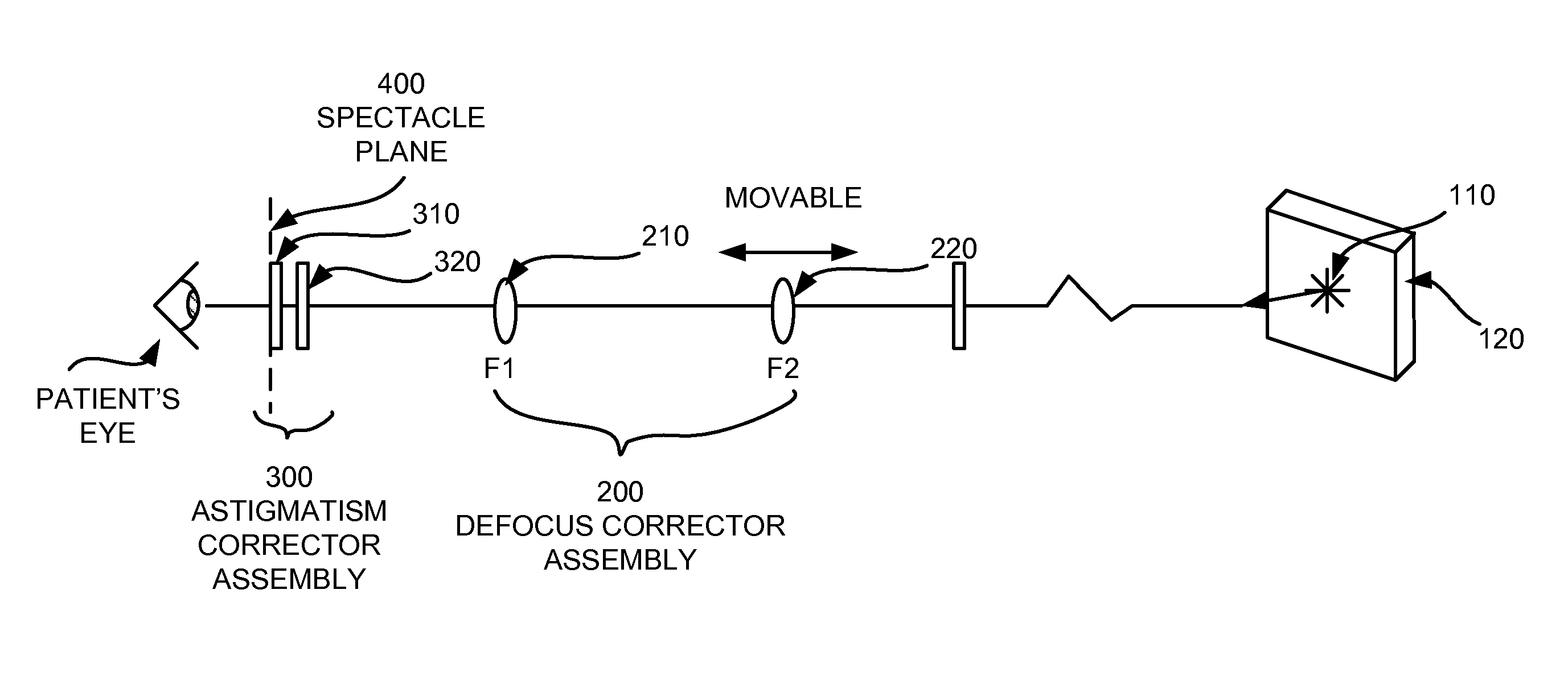
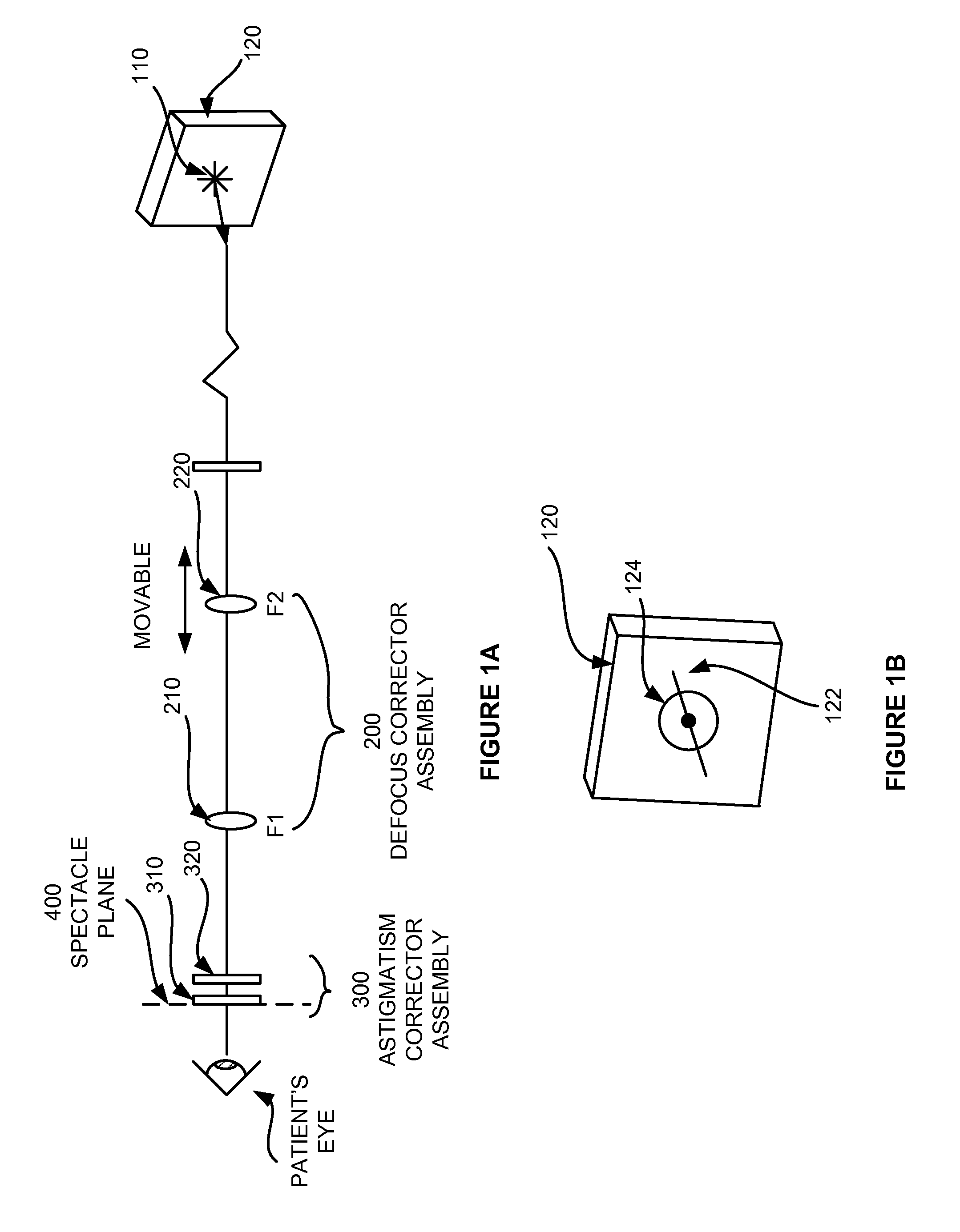
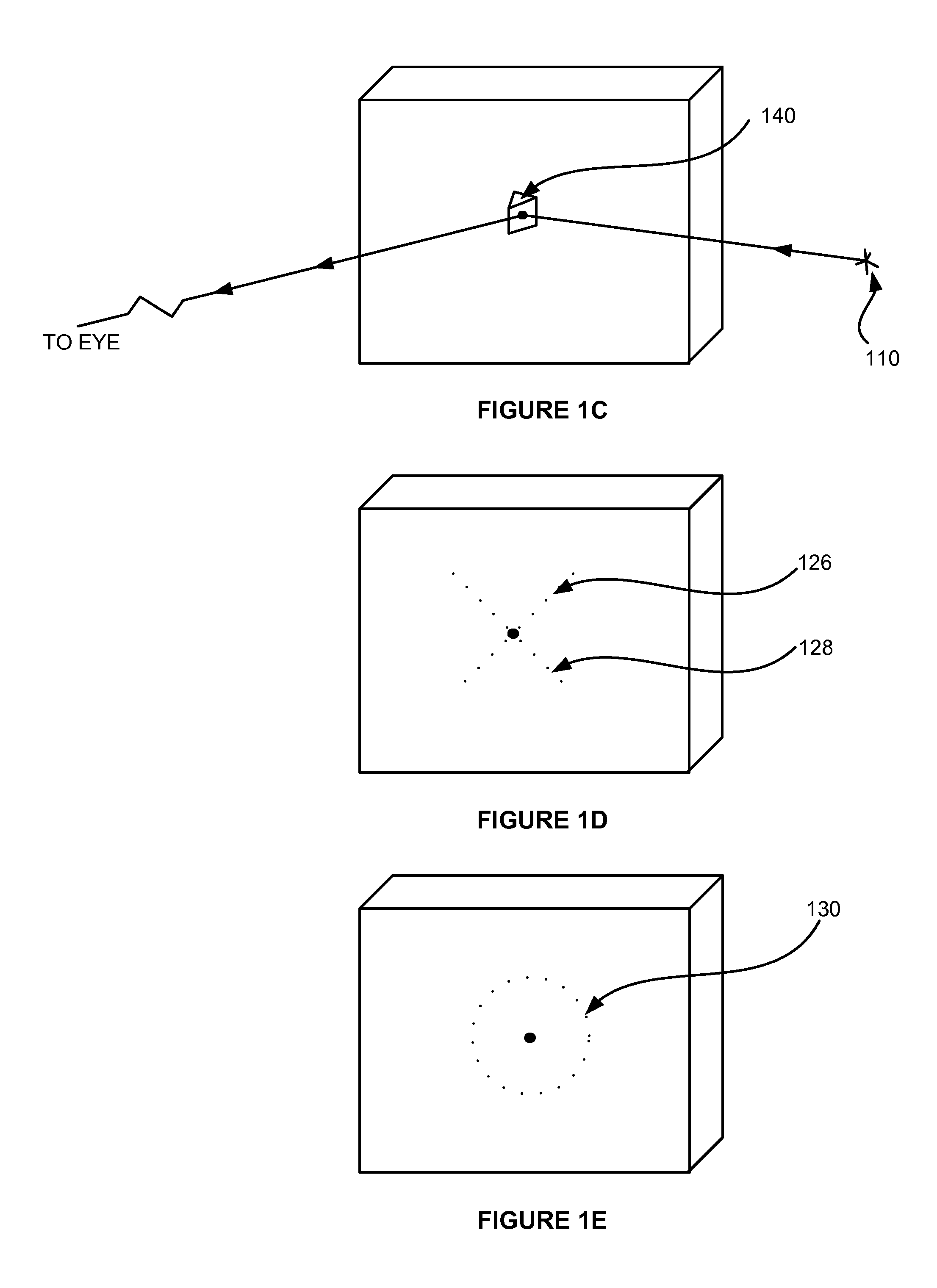
[0073] A subjective refraction method and a WF refraction device are provided that use defocus and astigmatism terms to correct both the second order (it is also referred to as the low order) and high order aberrations (sometime referred to as higher order, namely, third order and higher terms as described by Zernike polynomials). The spectacle prescription from the present refraction method is free from induced blur due to glazing at various angles.

[0074] The present refraction method provides a clear end point for the defocus. It also provides the axis angle of the astigmatism defects, and the optimal cylindrical angle that corrects the astigmatism. Furthermore, the present method enables the correction of HOA using defocus, astigmatism and axis, without inducing increases of HOA at various glazing angles. Furthermore, the device is capable of determining the least minus power point, not causing an over correction. Furthermore, the refraction process takes less time than using ph...


PUM


Abstract

A subjective refraction technique uses a plane wave light source including substantially a point as a viewing target. The refraction method provide for a number of distinct identifiable end points. By finding such end points the process leads to an aberration-corrected vision. A defocus corrector assembly (DCA) includes a lens that is moveable along an optical axis between a patient's eye and the point light source for adjusting defocus power until the patient indicates that the blurry image has become a relatively focused line image. An astigmatism corrector assembly (ACA) which is capable of continuously variable in its amplitude is provided including a pair of astigmatism plates for adjusting astigmatism power and axis angle. The ACA is adjusted until the patient indicates that the line image has become a substantially round image. A reference marker provides displayed items including a sweep line overlapping at the point source and having an orientation which is adjustable. The patient may subjectively control the sweep angle of the sweep line and indicate that the sweep line is aligned with the sharp line image of the point source, thereby providing axis angle data of astigmatism errors of the patient's eye.

Description

PRIORITY [0001] This application claims the benefit of priority to U.S. provisional patent application No. 60 / 773,758, filed Feb. 14, 2006, which is hereby incorporated by reference.BACKGROUND Subjective Refraction Methods [0002] Most optometrists and ophthalmologists use a phoropter to measure subjective refraction, and use an eye chart, typically a Snellen chart, as the viewing target. During the examination, the administrator seeks oral indication from the patient, to choose which one of the two lens-settings provides better acuity, with which the patient is able to read more letters. However, being able to recognize a letter, therefore, being able to read it, is quite different from seeing the letter sharp and crisp. Oftentimes the patient has difficulty deciding which one of the two choices 1 or 2 is “better”. This act of making a decision may in fact cause anxiety in some patients, since the answers ultimately will affect the prescription of his / her eyeglasses, and he / she is g...

Claims


Application Information

Patent Timeline
IPC IPC(8): G02C7/02
CPCA61B3/0285
Inventor LAI, SHUI T.
Owner LAI SHUI T
Why Eureka
Try Eureka