Image diagnostic apparatus, image processing apparatus, and program

a diagnostic apparatus and image processing technology, applied in the field of image diagnostic apparatus and image processing apparatus, can solve the problems of patient movement, lack of oxygen and causalgia, and inability to move the patient, so as to reduce the operation load on the operator and reduce the effect of motion artifacts

Active Publication Date: 2007-08-23
TOSHIBA MEDICAL SYST CORP
View PDF16 Cites 29 Cited by
  • Summary
  • Abstract
  • Description
  • Claims
  • Application Information

AI Technical Summary

Benefits of technology

[0007]It is an object of the present invention to reduce the operation load on an operator in pixel shift processing for reducing motion artifacts m...

Problems solved by technology

In DSA examination of the head of a patient, abrupt injection of a contrast medium into the patient may cause lack of oxygen and causalgia.
This causalgia causes the patient to move, and produces motion artifacts on subtraction images (also called DSA images).
In addition, some ...

Method used


Image

  • Image diagnostic apparatus, image processing apparatus, and program
  • Image diagnostic apparatus, image processing apparatus, and program
  • Image diagnostic apparatus, image processing apparatus, and program

Examples


first modification

(First Modification)

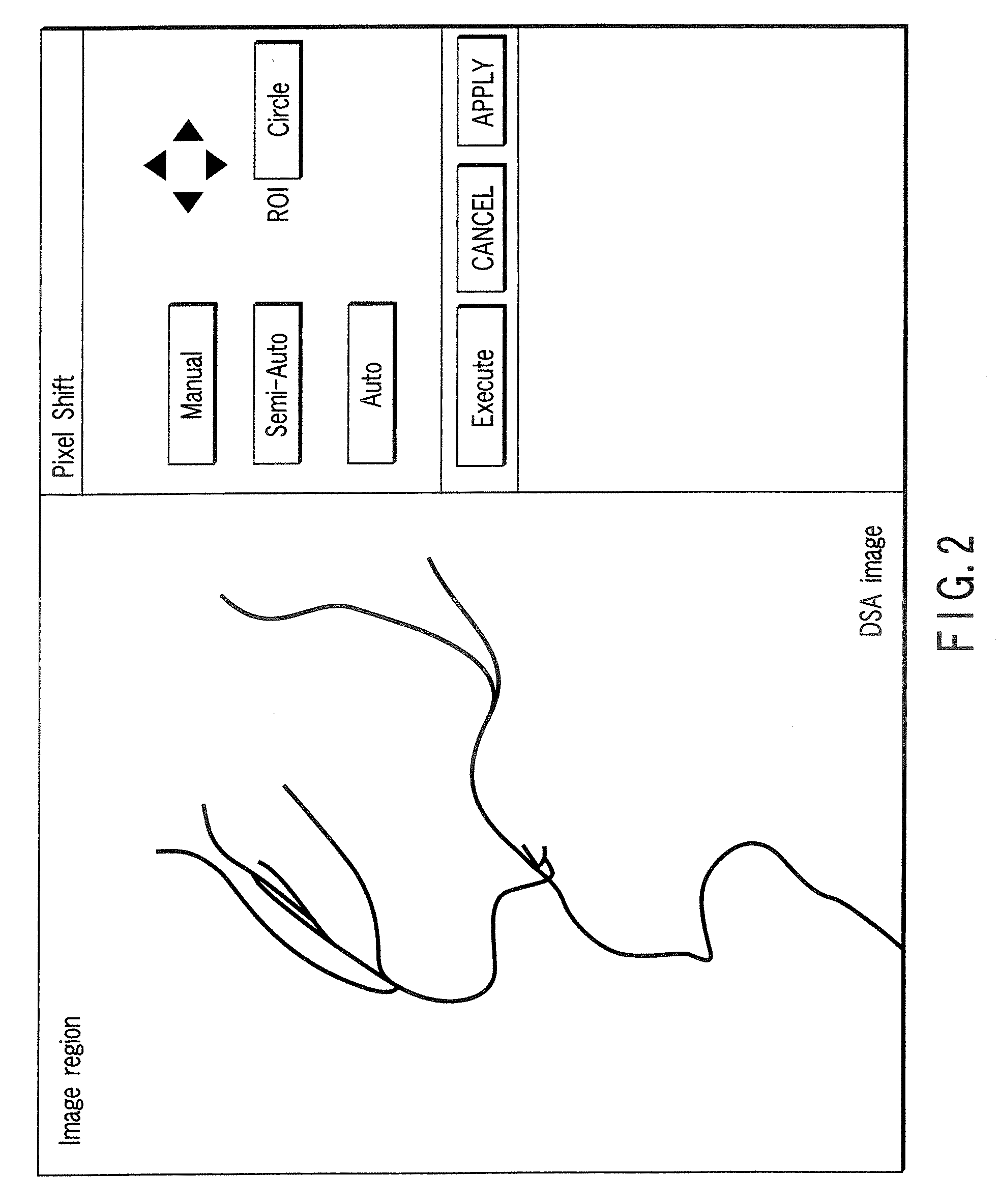
[0045]According to the above description, the above embodiment includes the automatic button. Even if, however, a region of interest ROI is set as an entire image with a semi-automatic button, it suffices to apply the algorithm for automatically setting a region of interest ROI, as shown in FIG. 5.

second modification

(Second Modification)

[0046]FIG. 6 shows a flowchart for a processing procedure based on a second modification. According to the above description, a region of interest is optimized with respect to only a display frame. However, it suffices to set an optimal region of interest ROI common to all the M contrast images.

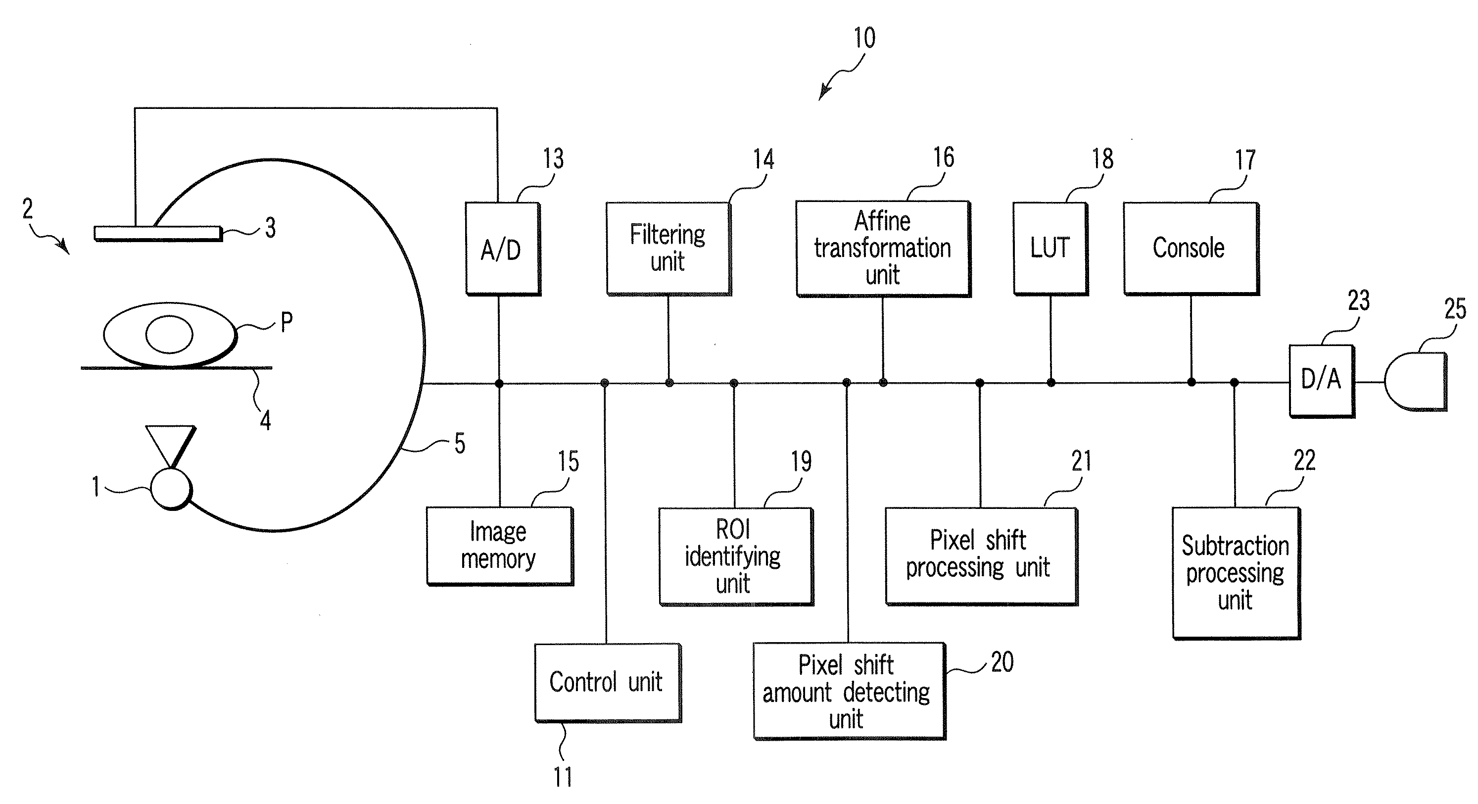
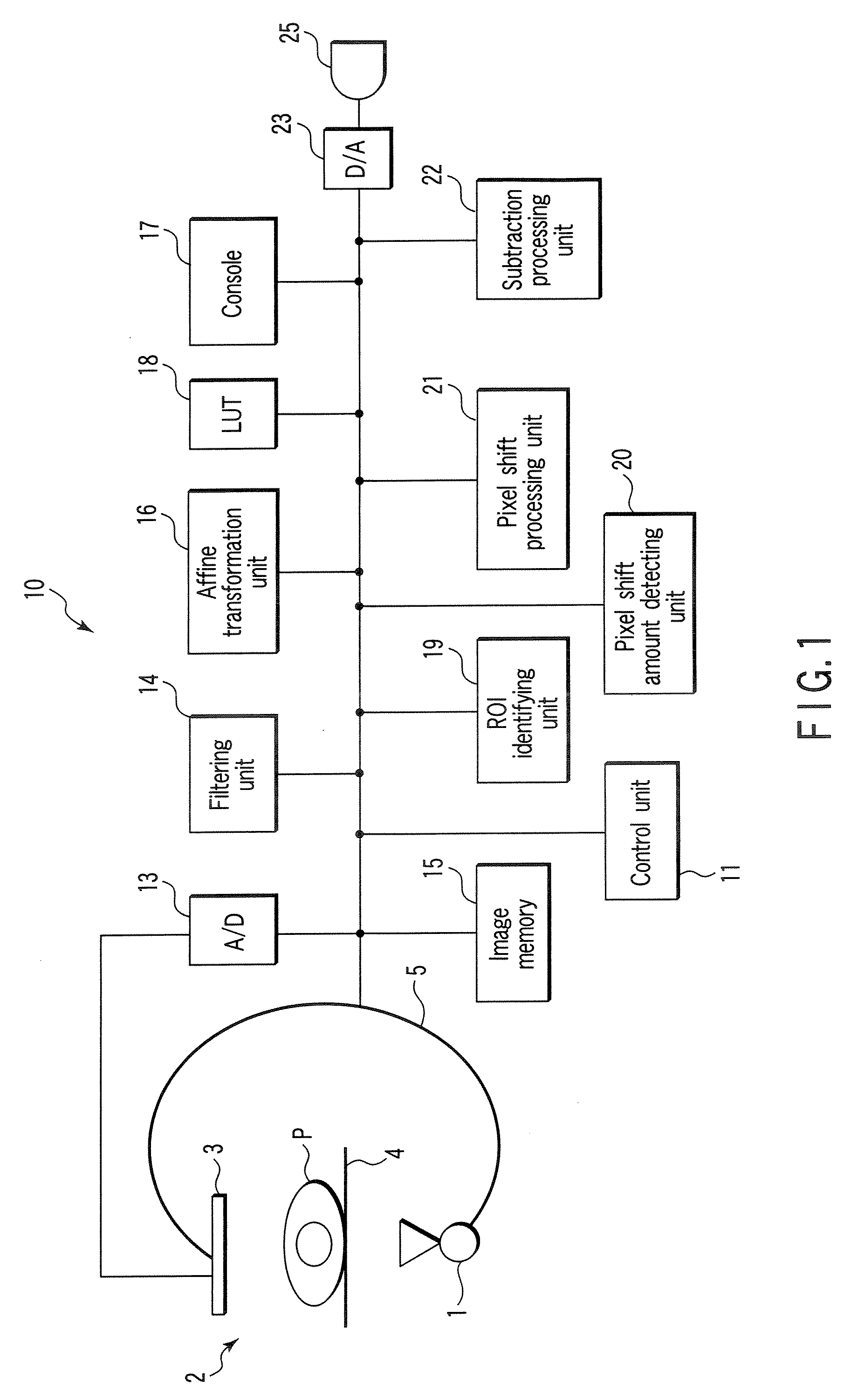
[0047]As in the above case, in setting the automatic mode, when the operator turns on the automatic button, the button is set in depressed state, and the apparatus starts processing. When the processing is complete, the button returns to the initial state. The following will describe a case wherein the apparatus acquire (M+1) images, and displays M subtraction images by setting one of the frames as a mask image and the M frames as contrast images. In this case, the mask image is a frame set by default. In general, the first frame is set as a mask image. First of all, a region of interest ROI is identified by using the M subtraction images. Thereafter, the apparatus detect...

third modification

(Third Modification)

[0057]According to the above description, it is a fundamental principle that a region of interest ROI is identified from an artifact occurrence region. However, it suffices to identify a region of interest ROI on the basis of a contrast-medium-injected region. In the ROI identification step, the control unit 11 obtains a contrast medium injection signal intensity Em(i, j) and a contrast medium injection signal frequency Fm(i, j) by using M generated subtraction images as follows:

Em(i,j)=∑k=1MINVf[Sk(i,j)](11)Fm(i,j)=∑k=1MINVg[Sk(i,j)+S](12)

where Sk(i, j) is the subtraction image of the kth frame, and S is a predetermined constant which discriminates a contrast medium injection signal from noise in Sk(i, j). Then, INVf(x) and INVg(x) are defined as follows:

INVf(x)={0:x≥0x:x<0(13)INVg(x)={0:x≥01:x<0(14)

[0058]Upon determining on the basis of the above result that Em(i, j)H, the control unit 11 registers the corresponding pixel as a contrast-medium-injected reg...


PUM


Abstract

An image diagnostic apparatus includes a radiography unit which generates a mask image and contrast images before and after the injection of a contrast medium, an image memory which stores the mask image and the contrast images, an ROI identifying unit which sets a region of interest from the mask image and the contrast images, a pixel shift amount detecting unit which detects a pixel shift amount between the mask and the contrast image upon localization to the region of interest, and a processing unit which shifts at least the mask image or the contrast image in accordance with the detected pixel shift amount and performs subtraction between the images.

Description

CROSS-REFERENCE TO RELATED APPLICATIONS[0001]This application is based upon and claims the benefit of priority from prior Japanese Patent Application No. 2006-042759, filed Feb. 20, 2006, the entire contents of which are incorporated herein by reference.BACKGROUND OF THE INVENTION[0002]1. Field of the Invention[0003]The present invention relates to an image diagnostic apparatus, image processing apparatus, and program which inject a contrast medium into a subject and perform subtraction processing between images before and after the injection of the contrast medium.[0004]2. Description of the Related Art[0005]In DSA examination of the head of a patient, abrupt injection of a contrast medium into the patient may cause lack of oxygen and causalgia. This causalgia causes the patient to move, and produces motion artifacts on subtraction images (also called DSA images). In this case, pixel shifting is manually performed, or semi-automatically performed upon designation of an ROI (Jpn. Pa...

Claims


Application Information

Patent Timeline
IPC IPC(8): H05G1/64
CPCA61B6/504
Inventor OHISHI, SATORU
Owner TOSHIBA MEDICAL SYST CORP
Why Eureka
Try Eureka