Continuous-focus ultrasound lens

a continuous-focus ultrasound and lens technology, applied in the field of medical imaging, can solve the problems of small target, e.g. a small malignant lesion, undetectable, affecting the signal-to-noise ratio, and the acoustical power that can be transmitted

Inactive Publication Date: 2007-08-23
B K MEDICAL
View PDF12 Cites 38 Cited by
  • Summary
  • Abstract
  • Description
  • Claims
  • Application Information

AI Technical Summary

Benefits of technology

[0011] The present invention is an ultrasound transducer with an acoustic lens intended for medical imaging providing continuous focusing in the elevation plane over a predetermined imaging range. The transducer comprises an ultrasound element and an acoustic lens, said lens having a cross sectional profile comprising a curved portion with a preferably circular shape providing a single focus at a first focal depth, and first and second linear portions on either side of said curved portion, said linear portions providing continuous focusing at imaging ranges after said first focal depth of said curved portion. At the interfaces between said curved portion and said linear portions, the slope is continuous such that the surface profile of the lens is smooth. Preferably, said lens is manufactured as a unity. Thereby is obtained a lens surface which is free of abrupt changes not caused by limited accuracy of the manufacturing equipment.

Problems solved by technology

If a wide elevation beam is produced by the transducer, a small target, e.g. a small malignant lesion, may be undetectable due to the surrounding tissue scatters.
Additionally, the size of the elevation aperture limits the acoustical power that can be transmitted to the object by each element, and hence the signal-to-noise ratio obtainable.
Furthermore, it determines the element sensitivity in receive mode, again affecting the signal to noise ratio.
The slice thickness and contrast resolution of such lenses are significantly worse outside the focal region than their performance at the focal point.
Multirow transducers (array transducers with several rows of elements) have been developed to obtain better control of the elevation beam profile, enabling dynamic receive processing, but at the expense of increased system complexity (more receive channels, analog-to-digital converters) and cost.
Commonly, the prior art described hereinbefore involve increased complexity either in manufacturing of the transducer elements or in system complexity.

Method used


Image

  • Continuous-focus ultrasound lens
  • Continuous-focus ultrasound lens
  • Continuous-focus ultrasound lens

Examples


Embodiment Construction

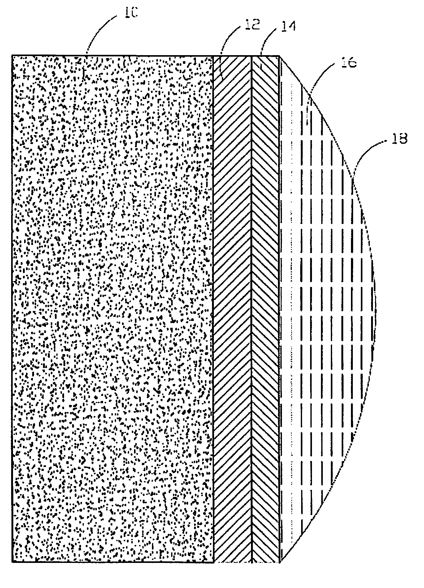
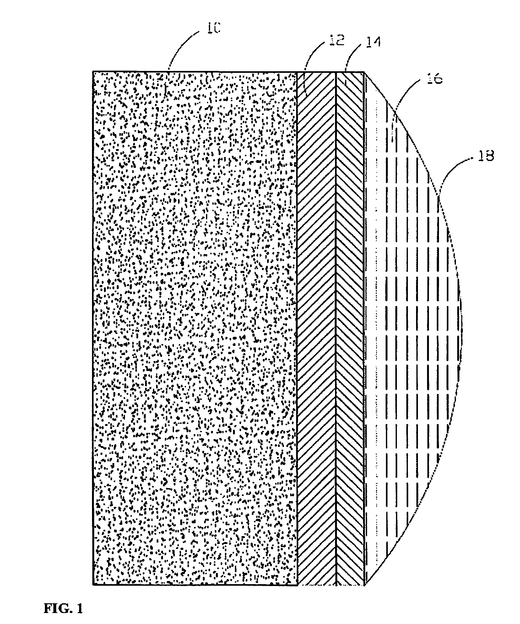
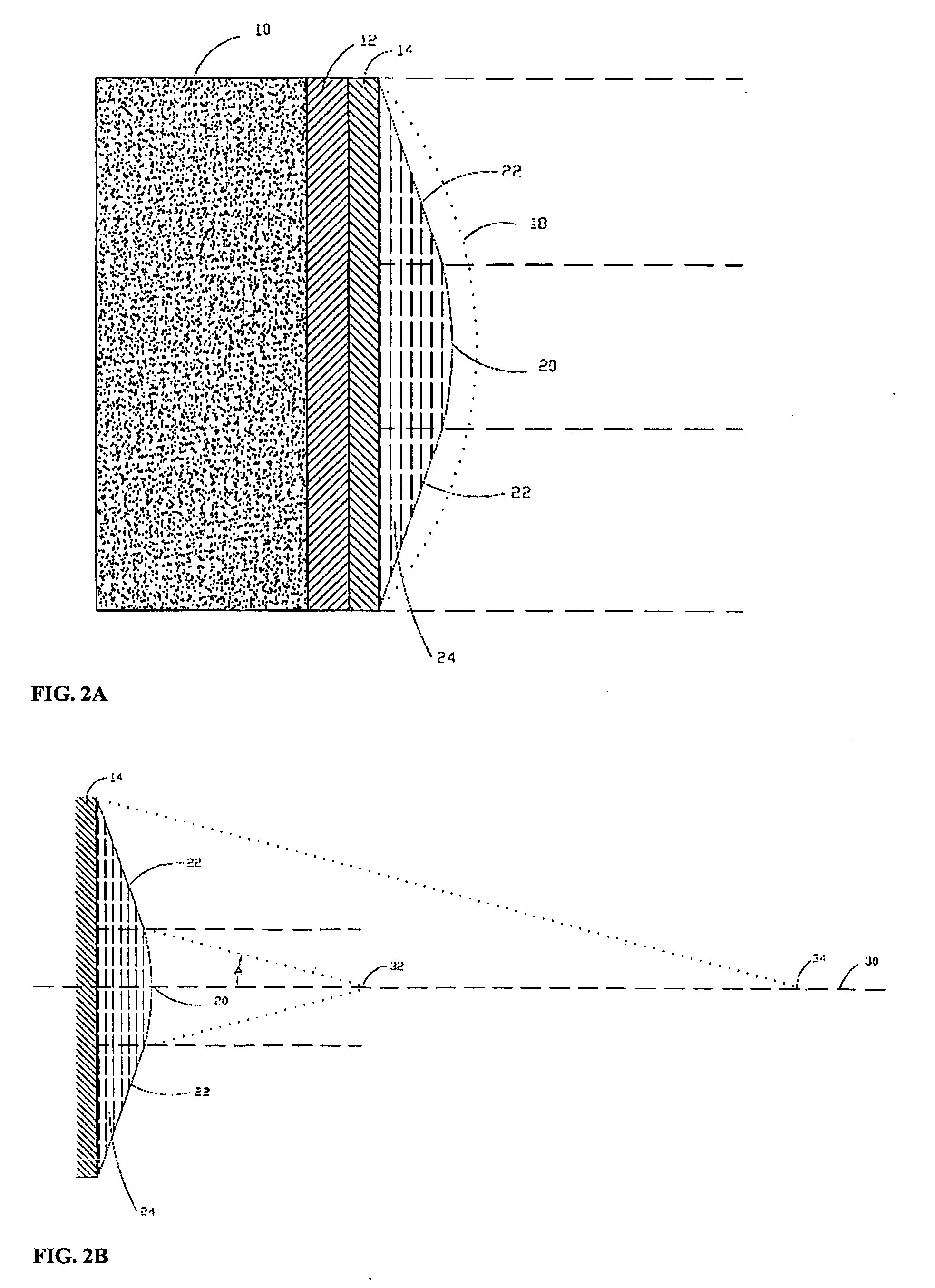
[0020] The invention is related to the field of medical ultrasound imaging, and in particular, the area of improving the elevation beam profile of the ultrasound transducer to obtain better slice thickness and image contrast resolution by means of extending the depth of focus. The invention is an ultrasound transducer comprising an acoustic element and an acoustic lens. Said element has a substantially uniform frequency amplitude characteristic across its spatial extent and transmitting an ultrasound beam when excited. Said acoustic lens is positioned in front of said element, said lens having a cross sectional profile comprising (1) a curved portion with a curved front surface and a back surface facing said transducer element, said curved lens portion providing a focal point at a first focal range, and (2) a pair of linear portions with linear front surfaces and back surfaces facing said transducer element, said linear portions positioned on either side of said curved portion, and ...


PUM


Abstract

The depth of focus in the elevation plane of an acoustic ultrasound transducer is extended. The ultrasound transducer comprises an acoustic element, said element having a substantially uniform frequency amplitude characteristic across its spatial extent and transmitting an ultrasound beam when excited, an acoustic lens positioned in front of said element, said lens having a cross sectional profile comprising (1) a curved portion with a curved front surface and a back surface facing said transducer element, said curved lens portion providing a focal point at a first focal range, and (2) a pair of linear portions with linear front surfaces and back surfaces facing said transducer element, said linear portions positioned on either side of said curved portion, and said linear portions providing continuous focusing at imaging ranges after said first focal depth of said curved portion. The broadband frequency characteristic of said element means that all frequencies are focused at all focal points, which makes the invention particularly useful for harmonic ultrasound imaging.

Description

[0001] The invention is related to the field of medical ultrasound imaging, and particularly the area of improving of the elevation beam profile of ultrasound transducers to obtain better slice thickness and image contrast resolution by means of extending the depth of focus. The elevation beam profile is described by the slice thickness perpendicular to the imaging plane, often referred to the elevation beamwidth, and the sidelobe characteristics of the beam perpendicular to the imaging plane. BACKGROUND OF THE INVENTION [0002] Ultrasound imaging is an established modality in the field of medical imaging providing real-time images of soft human tissue and blood flow. The images are generated using a hand held transducer comprising either a single element or most commonly an array of elements arranged in a single row (1D transducers). For array transducers, cross-sectional images are conventionally created by transmitting focused beams in multiple directions sequentially using all or...

Claims


Application Information

Patent Timeline
Patent Type & Authority Applications(United States)
IPC IPC(8): A61B8/14
CPCG10K11/30
Inventor BAGGE, JAN PETER
Owner B K MEDICAL
Why Eureka
Try Eureka