Fluid-powered prosthetic apparatus

Inactive Publication Date: 2007-08-23
ELKINS INNOVATIONS
View PDF15 Cites 38 Cited by
  • Summary
  • Abstract
  • Description
  • Claims
  • Application Information

AI Technical Summary

Benefits of technology

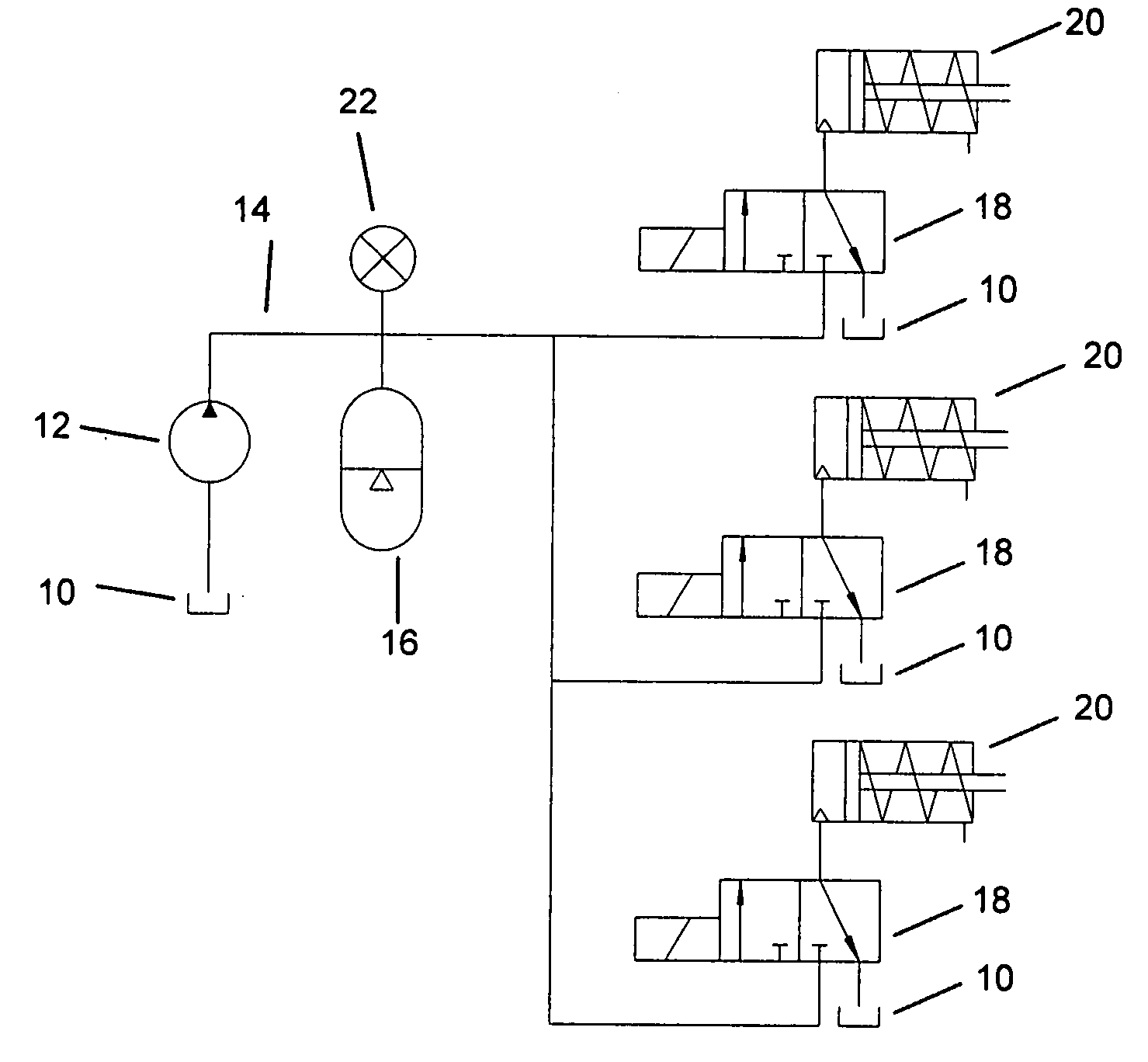
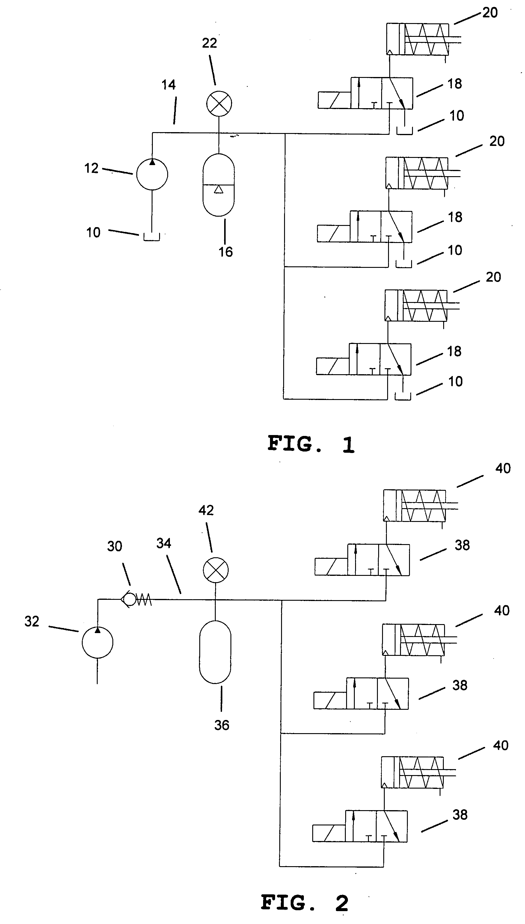
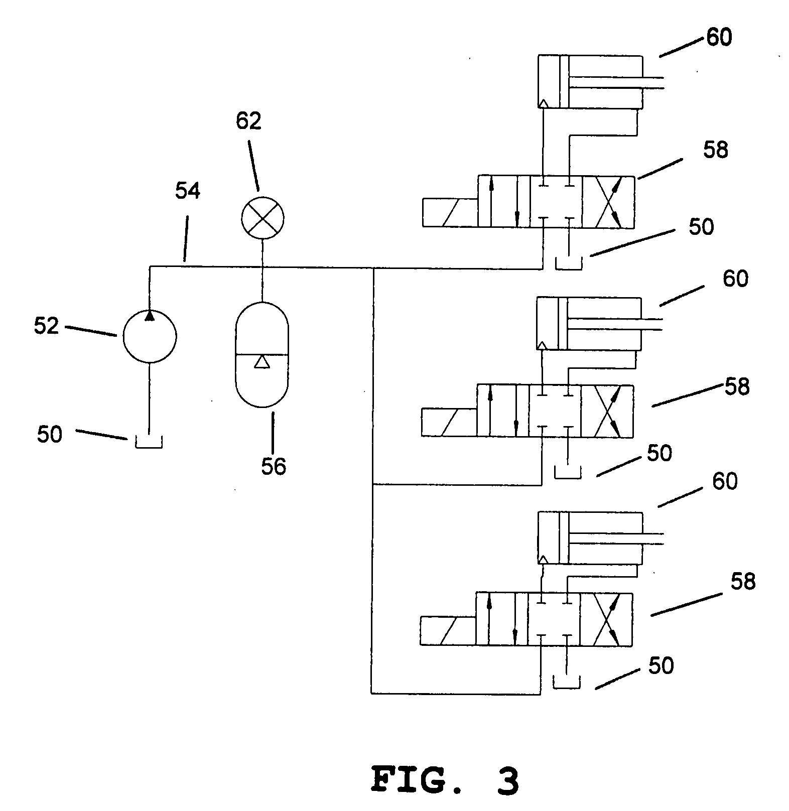
[0015]In one aspect of the invention there is provided a prosthetic device having a plurality of independently movable members using a fluid powered system having a single motor (for charging the fluid pressure). The pressurized fluid can be easily transported through or around the device to provide mo

Problems solved by technology

While prosthetic devices exist to assist these individuals, most are little more than glorified pincers which are too heavy and lack functionality.
In fact, less than 50% of eligible amputees choose to not wear a prosthetic device because of these limitations.
Most prosthetic hands are large and heavy because they employ a single, permanent magnet electric motor to motivate the hand.
Due to the necessity of providing a certain level of force, this implementation practice necessitates the use of a motor that is large (as compared to the available volume), heavy (as compared to a human hand), and expensive.
Though the use of a single, large electric motor suffices for current prosthetic device, this practice cannot be extended to hands with multiple, independent motions.
Most prosthetic hands lack functionality because they provide only one motion (degree of freedom).
Others have endeavored to address

Method used


Image

  • Fluid-powered prosthetic apparatus
  • Fluid-powered prosthetic apparatus
  • Fluid-powered prosthetic apparatus

Examples


Example

[0026]There are two technical issues that have restricted existing prosthetic hands to being limited to a single degree of freedom—the inability to provide a reasonable means for controlling additional degrees of freedom and the engineering challenges inherent in packaging multiple motors, batteries, etc within the volume of the prosthetic device. In the context of this application, the term ‘prosthetic device’ shall mean all components of the artificial limb, including the socket, terminal device, etc.; and the term ‘within’ shall mean inside the outer periphery in such a manner that the device retains its appearance of being natural.

[0027]The first problem has been addressed by Jeffrey Elkins of Elkins Innovations, Inc. in a patent application entitled “Foot-Operated Controller,” Publication No. US 2004 / 0078091 A1. This patent application describes a family of controllers that provide means to control prosthetic devices with multiple degrees of freedom (i.e., independent movement)...


PUM


Abstract

An improved prosthetic device having a plurality of independently movable members that operate at peak efficiency for a majority of the time that it is in the on state, thereby extending battery life, includes at least two members that are independently movable, a fluid actuator associated with each of the independently movable members for effecting movement, a fluid pump or compressor having a fluid inlet and a compressed or pressurized fluid outlet, an electrical motor coupled to the pump or compressor, a fluid conveying conduit between the pump or compressor outlet and the actuator, a fluid reservoir in communication with the conduit between the pump or compressor outlet and the actuator, and at least one valve associated with each of the independently movable members.

Description

CROSS REFERENCE TO RELATED APPLICATIONS[0001]This application claims the benefit of provisional patent application Application No. 60 / 774,837, filed Feb. 17, 2006 by Gerald P. Roston, the entire disclosure of which is incorporated herein by reference.BACKGROUND OF THE INVENTION[0002]1. Field of the Invention[0003]This invention relates to prosthetic devices, specifically those with a plurality of motions.[0004]2. Description of the Related Art[0005]In the US there are 90,000 people who, due to birth defect, accident, or disease, have lost the use of one (or both) of their hands. While prosthetic devices exist to assist these individuals, most are little more than glorified pincers which are too heavy and lack functionality. In fact, less than 50% of eligible amputees choose to not wear a prosthetic device because of these limitations. This fact clearly indicates that upper extremity amputees are an underserved group with respect to the technology available to improve their lives.[00...

Claims


Application Information

Patent Timeline
IPC IPC(8): A61F2/72A61F2/66
CPCA61F2/58A61F2/583A61F2/585A61F2/586A61F2/68A61F2002/7655A61F2002/704A61F2002/741A61F2002/745A61F2002/747A61F2002/748A61F2002/701A61F2/70A61F2/741A61F2/74A61F2/748
Inventor ROSTON, GERALD P.TUBERGEN, RENARD G.
Owner ELKINS INNOVATIONS
Why Eureka
Try Eureka