Eureka AIR delivers breakthrough ideas for toughest innovation challenges, trusted by R&D personnel around the world.

Modular machine and corresponding method for dynamically configuring the topology of said machine

a technology of dynamic configuration and topology, applied in the field of modules and corresponding methods for dynamic configuration of topology of machines, can solve the problems of relatively complex and/or costly process, system (control device and other machine modules) no longer knows how to reach the communication partner in the topology, etc., and achieves the effect of simplifying the engineering process

Inactive Publication Date: 2007-08-23
SIEMENS AG
View PDF3 Cites 5 Cited by
  • Summary
  • Abstract
  • Description
  • Claims
  • Application Information

AI Technical Summary

Benefits of technology

[0006] An object of the present invention is therefore to make it easier to reconfigure a modular machine.
[0009] The inventive dynamic configuring of the topology of the communications network of the modular machine has the advantage that, when the communications topology is reconfigured, machine operation does not need to be interrupted and it is possible for the communications to be configured during the runtime of the machine.
[0013] A preferred method for putting a modular machine into service therefore begins with the step of configuring the interaction of the machine modules, prior to the startup stage of the modular machine, by means of an engineering system for an automation task to be solved without taking the communications topology of the individual machine modules into account, followed by the step of dynamically configuring the communications network with which the machine modules are interconnected, according to the above described configuration method. This considerably simplifies the engineering process prior to the machine startup stage.

Problems solved by technology

The same problem arises if the connection of a communications partner to the communications network of a modular machine is re-arranged.
Again the system (control device and other machine modules) no longer knows how the communications partner can be reached in the topology.
However, this is a relatively complex and / or costly process and involves interrupting machine operation.

Method used


Image

  • Modular machine and corresponding method for dynamically configuring the topology of said machine
  • Modular machine and corresponding method for dynamically configuring the topology of said machine

Examples


Embodiment Construction

[0015] The exemplary embodiment described in greater detail below is a preferred embodiment of the present invention.

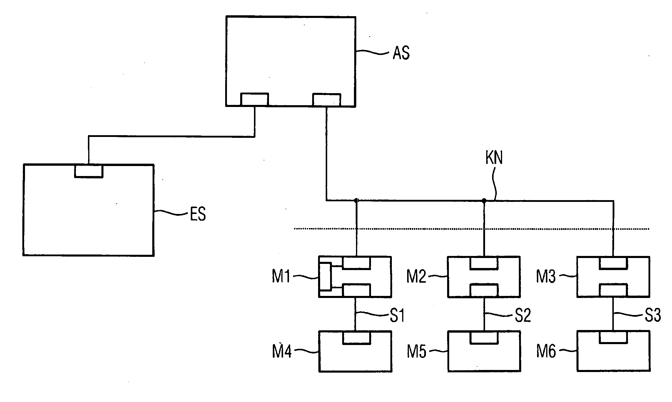
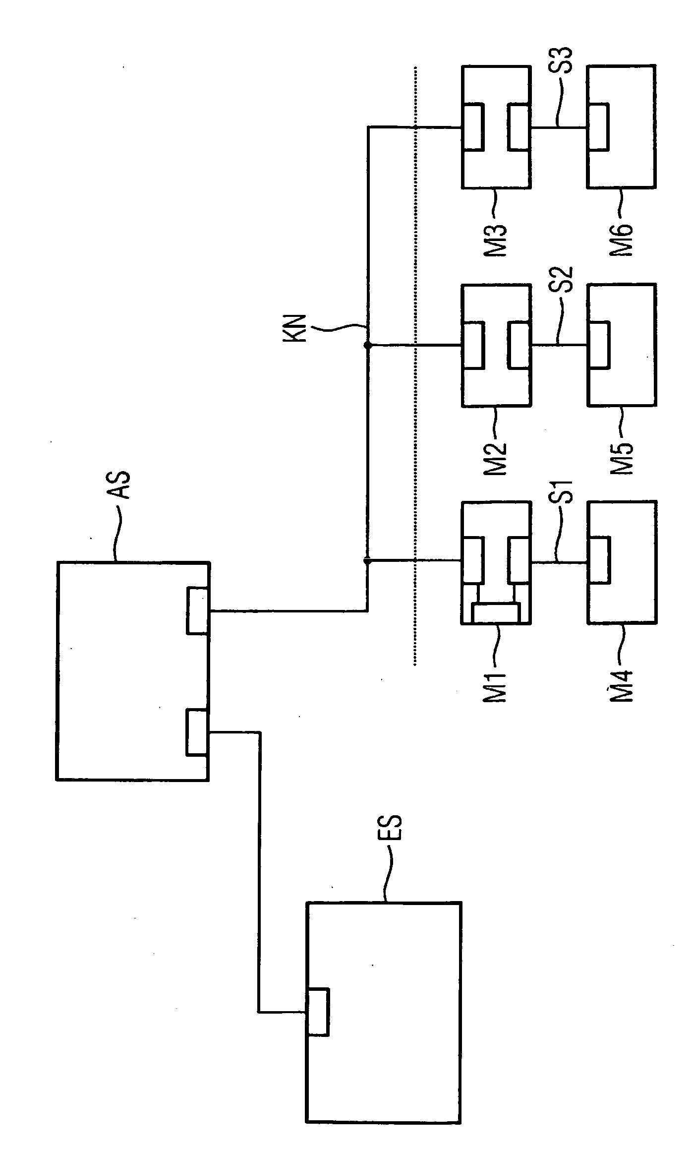
[0016] A flexible, modular machine typically consists of machine modules M1 to M6 as shown in the figure. The machine modules M1 to M3 are connected to a communications network KN. The possible separation between the machine modules and the communications network KN is indicated in the figure by a dotted line.

[0017] The machine modules M1 and M4 are interconnected via a communications subnetwork S1, the machine modules M2 and M5 via a communications subnetwork S2 and the machine modules M3 and M6 by a communications subnetwork S3. The subnetworks S1 to S3 are therefore connected only indirectly to the communications network KN via the relevant machine modules M1 to M3. Obviously the respective subnetworks S1 to S3 can each contain any number of further subnetworks. It is likewise conceivable for further modules to be connected to the modules M4 to M6 via additional ...


PUM


Abstract

In one aspect, a method for dynamic configuration of a modular machine, whose modules are interconnected and connected to a control unit via a communications network is provided in order to facilitate the modification of a machine configuration in automated systems. According to the method, during the operation of the machine, one of the communications partners determines the communications partners in the communications network. The communications partner then generates a suitable communications configuration and activates said configuration. This permits the communications configuration or design to be automatically executed, even during the operation of the machine.

Description

CROSS REFERENCE TO RELATED APPLICATIONS [0001] This application is the US National Stage of International Application No. PCT / EP2005 / 051154, filed Mar. 15, 2005 and claims the benefit thereof. The International Application claims the benefits of German application No. 102004015240.3 DE filed Mar. 24, 2004, both of the applications are incorporated by reference herein in their entirety. FIELD OF INVENTION [0002] The present invention relates to a method for dynamically configuring a topology of a modular machine whose modules are connected to one another and to a control device via a communications network. The present invention additionally relates to a modular machine of this kind. BACKGROUND OF INVENTION [0003] A modular machine for automated production processes is usually configured, in terms of its mode of operation, for the automation task to be solved. This means that, among other things, the individual modules of the machine are assigned corresponding tasks. This configuring...

Claims


Application Information

Patent Timeline
Patent Type & Authority Applications(United States)
IPC IPC(8): G06F3/00G05B19/042G05B19/418
CPCG05B19/0423G05B19/41845G05B2219/25296G05B2219/15007G05B2219/25096G05B2219/15004Y02P90/02
Inventor DANZ, MIKROEXTRA, JOHANNES
Owner SIEMENS AG
Why Eureka
Eureka Blog
Learn More