Block For Forming Wall And The Wall Thus Formed

a technology of forming walls and blocks, applied in the field of blocks, can solve the problems of inconvenient use, shortening the service life of the building, and not solving the existing problem, and achieve the effects of improving the non-watertight and soil-keeping effect, avoiding water leakage, and avoiding water leakag

Inactive Publication Date: 2007-08-30
WANG RONGXUN
View PDF11 Cites 28 Cited by
  • Summary
  • Abstract
  • Description
  • Claims
  • Application Information

AI Technical Summary

Benefits of technology

[0030] Theoretical model of leak proof is that: when the water on the surface of the wall flows into the horizontal masonry joint and then into the vertical masonry joint, or directly into the vertical masonry joint, it flows inwardly and downwardly into the wall under the gravity and wind pressure, its space-time trajectory of leakage follows the rule of “high to low”. At this time, the top of the vertical masonry joint (slot) on the wall (i.e., the bottom foot of the block on the top of the vertical masonry joint) is usually the vertex of the space-time trajectory of leakage. The supporting slopes are provided on the block, the left and right supporting slopes form the mid ridge. When the water flows along the space-time trajectory to the ridge of the block under the vertical masonry joint, the top of the mid ridge can cut off the space-time trajectory to realize leak proof. Obviously, the larger the size of the ridge is, the better of the leak-proof effect is.
[0031] As known to all, the faster the muddy water is, the fewer the sediments are; the slower the muddy water is, the more the sediments are. The space-time trajectory of the muddy water follows the rule of “high to low”. The non-watertight and soil-keeping theoretical model is that: the supporting slope are provided on the block, the left and right supporting slopes form the mid ridge; the top of the ridge can cut off the space-time trajectory of the muddy water to make the water flowing into the horizontal masonry joints and the vertical masonry joints can only overflow the ridge of the block; the soil in the water is blocked by the supporting slope; the larger the mid ridge is, the better the non-watertight and soil-keeping effect is.
[0032] The block, which complies with this theoretical model, is a longitudinally profiled member. It shall have a top surface, a bottom surface and two end surfaces. The cross section of the block shall be in a shape of down-flared recess. The top surface of the block has a mid ridge higher than two sides of the surface so that the left and right supporting slopes are formed. The top and bottom surfaces are formed such that: when the block is overlapped with a analogous block thereunder to form the walls, the top surface of the underlying block is engaged with the bottom surface of the upper block. The left and right supporting slopes are used as a blocking structure and interlock the vertically adjacent blocks. The projecting size of the mid ridge can cut off the space-time trajectory.
[0033] When the standards for leak proof or non watertight and soil keeping are determined, the space-time trajectory can be determined, and then the projecting size of the mid ridge, which cuts off the space-time trajectory, can be determined. The larger the ridge is, the better the blocking effect is, and the better the water-stop, leak-proof or the non-watertight and soil-keeping effects are. The ideal leak-proof and non-watertight and soil-keeping effects are: the blocks are shaped and sized such that: when three analogous blocks are overlapped vertically, the top of the ridge of the bottommost block is higher than the bottom foot of the uppermost block.

Problems solved by technology

The measures for realizing leak proof, non watertight and soil keeping of the wall are important problems in the field of construction.
However, there are some disadvantages, such as complicated production, inconvenience of use, shortcoming of functions and so on, thus not solving the existing problem.
As defined in claim 1, the ridge, the slot and the notches of the block take the functions of “inlay” and “lap joint”, however, they do not solve the leak proof of the vertical masonry joints in different weather environments.
It merely has the function of one-side leak proof, suitable for the dry masonry or laid-dry method and unsuitable for the sticking masonry.
And, the dry masonry thus formed is not suitable for the main wall, since it has a bad lateral stability.
It is inconvenient to fire this block in the form of bar.
If the small ridges and slots are changed into a horizontal plane to make the sticking masonry convenient, then the block will lose the function of mutual engagement, and thus making the lateral instability more easy.
When constructed with stones and bricks by mortar, the extending ply of the mortar on drainage bevel surface of every block is inconsistent.
If the extending ply of the mortar is regulated by applying force vertically onto the drainage bevel surface, the wall has the possibility of lateral instability.
However, if the extending ply of the mortar is not regulated, the surface of the wall will not be smooth because of the uneven projection of the block.
However, this can not solve the problems of craze and leak proof.
There is no way for leak proof between the masonry block and the upper, bottom surfaces of the frame girder yet.
However, the sealing cincture and waterproof ointment are prone to be aged.
There is another leak-proof measure, i.e., providing a sweat-soldering leak-proof layer between the wall and the rock, however, this measure usually results in leakage because of the loose engagement of the jointing, drop of the jointing, or craze of the leak-proof layer due to a distortion of the building.

Method used


Image

  • Block For Forming Wall And The Wall Thus Formed
  • Block For Forming Wall And The Wall Thus Formed
  • Block For Forming Wall And The Wall Thus Formed

Examples


Embodiment Construction

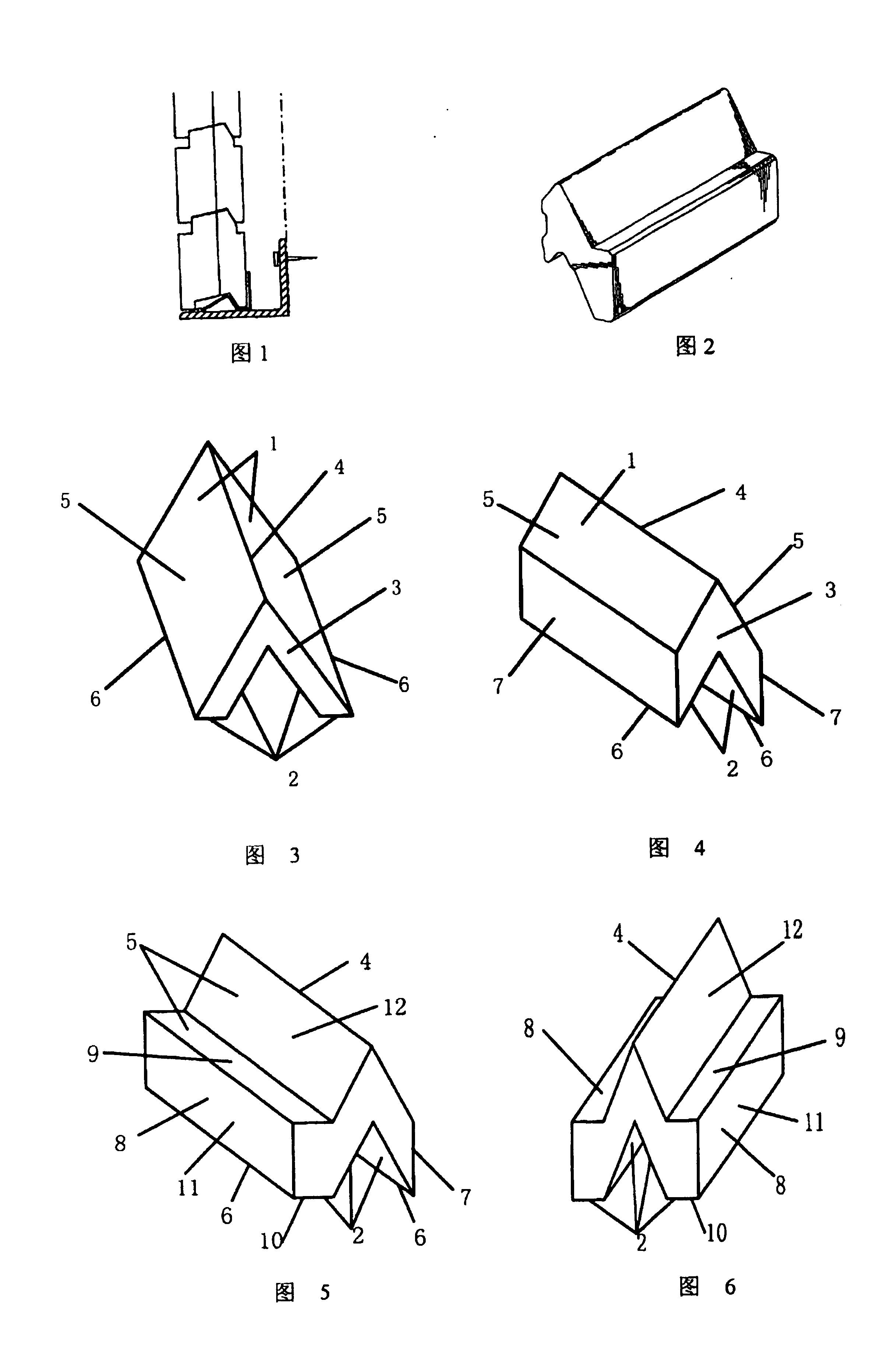
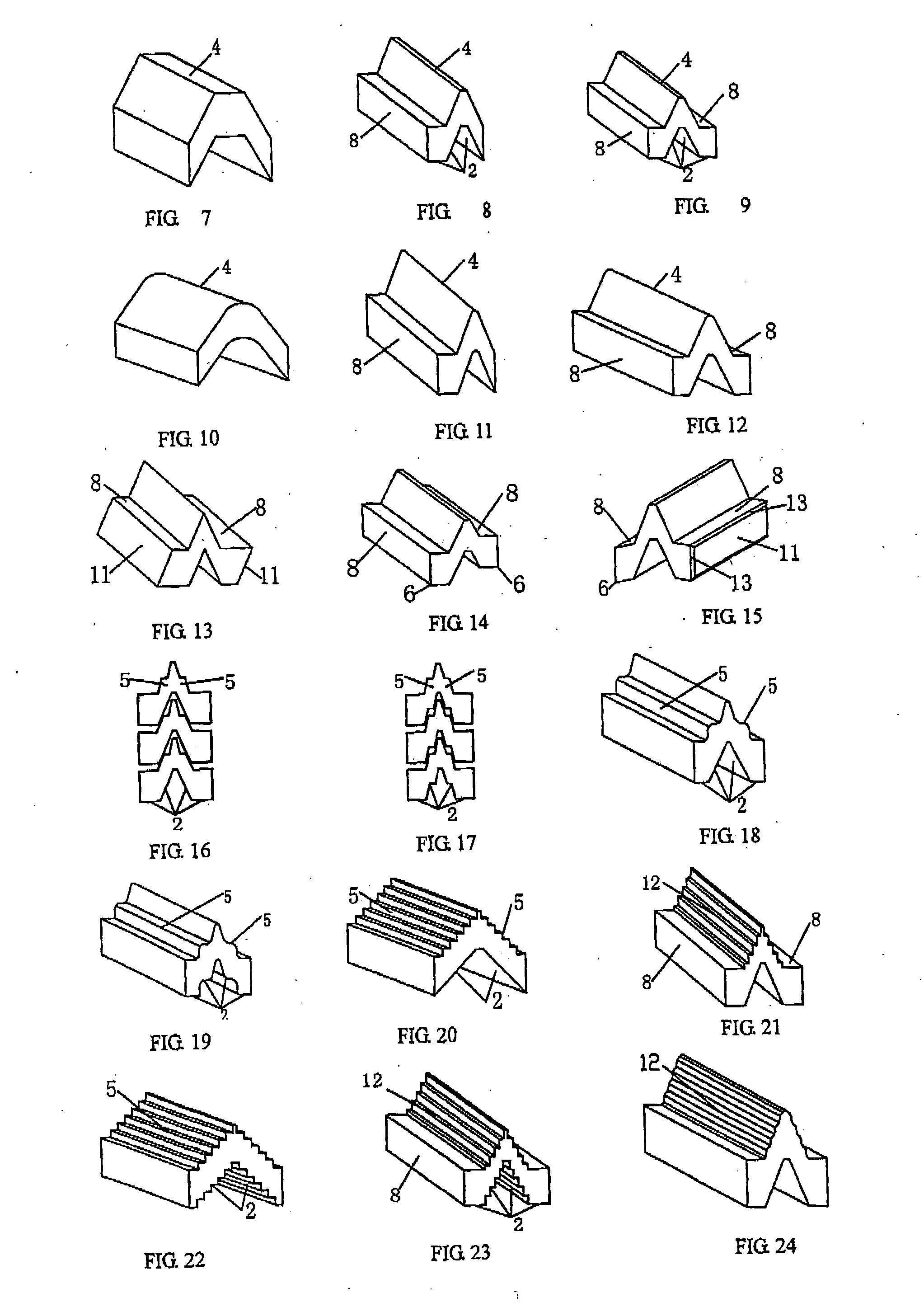
[0103] The following are the further descriptions of the invention with reference to the figures. However, the figures, the ways described and the technical parameters cannot be understood as limitations to the present invention.

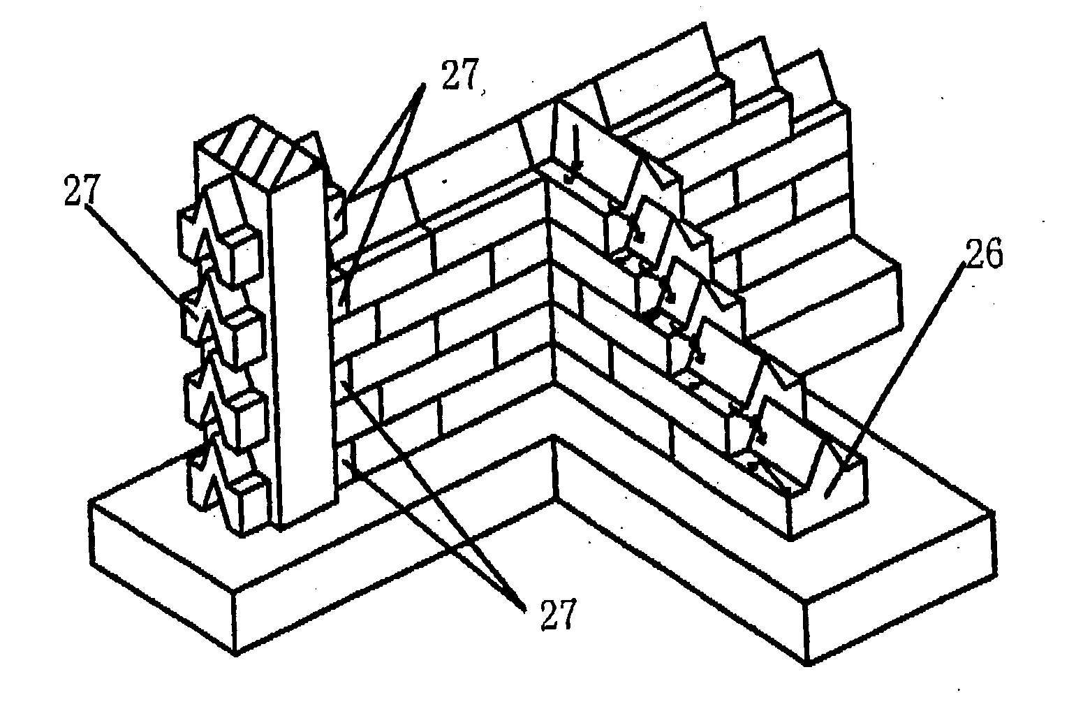
[0104]FIGS. 3 and 4 show the basic structural of the block of the invention. The block is a longitudinally formed (longitudinal profiled) product. The cross section of the block is of a downward-flared shape, and includes a top surface 1, a bottom surface 2 and two end surfaces 3. The top surface has a mid ridge 4 higher than the two sides of the surface so that a left supporting slope 5 and a right supporting slope 6 are formed. Both the top of the mid ridge and the bottom surface are of sharp-angled shape. As shown in FIG. 3, the planes at two sides of the bottom surface of the block are horizontal planes. Two bottom feet 6 are at the intersections between the top surface and the bottom surface. The block of FIG. 4 has a lateral connecting surface 7, the ...


PUM


Abstract

A kind of block for building wall and the wall built with said blocks. There are many analogous blocks laid to overlap and stagger with upper/nether block continuously in said wall. The block extends lengthways and comprises top surface (1), bottom surface (2) and two end surfaces (3); the cross section thereof on the whole is a converse trumpet shape; the top surface (1) has a mid ridge (4) higher than the two sides of the surface so as to form the left/right supporting slope (5); the top surface (1) and the bottom surface (2) are formed in this way: when a block overlap with a analogous block thereunder to form a wall, the left and right supporting slope (5) become a blocking structure to lock the two blocks neighbored up and down, the raised dimension of the mid ridge (4) can cut off space-time trochoid. This invention also provides the assistant blocks, which cooperate with said blocks when building wall.

Description

TECHNICAL FIELD [0001] This invention relates to a block for forming constructing walls and constructing roofs, as well as walls thus formed. In particular, it relates to a block capable of forming the walls, which are double-side leak-proof and water-stop. BACKGROUND ART [0002] The measures for realizing leak proof, non watertight and soil keeping of the wall are important problems in the field of construction. [0003] The leaking portions are: 1) leakage of the masonry joint of the wall, 2) leakage between the masonry block and the frame pillar in the construction of framework, 3) leakage between the masonry block and the top surface of frame girder in the construction of framework, 4) leakage between the masonry block and the bottom surface of frame girder in the construction of framework. [0004] There are two ways for realizing leak proof of the masonry joints in walls. One is to reduce the craze of the masonry joint. The other one is to adopt a design of a concave-convex structu...

Claims


Application Information

Patent Timeline
Patent Type & Authority Applications(United States)
IPC IPC(8): E04B5/00E04B2/02E04B2/08
CPCE04B2/08E04B2002/0265E04B2002/021
Inventor WANG, RONGXUN
Owner WANG RONGXUN
Why Eureka
Try Eureka