Method for joining ends of sections of pipe

a technology of pipe ends and pipe ends, which is applied in the direction of hose connection, pipe heating/cooling, manufacturing tools, etc., can solve the problems of difficult expansion of pipe ends in order to increase the internal diameter of the pipe, limited to connecting pipes of different diameters, and difficult to expand the pipe in order to achieve good matching and prevent separation

Inactive Publication Date: 2011-04-05
BRAYMAN SEMYON +1
View PDF6 Cites 12 Cited by
  • Summary
  • Abstract
  • Description
  • Claims
  • Application Information

AI Technical Summary

Benefits of technology

[0018]The tapered mating surfaces preferably have a 50:1 taper that provides for self-locking of the pipe ends after being assembled to further assist in preventing separation. A reversible forming tool device is preferably used to form the mating tapered surfaces of both the male and female pipe ends to insure a very good matching to insure a leakproof joint.
[0025]The complementary end shapes ensures substantially equal resistance to plastic expansion of the joined pipes along their lengths including in the joints in order to allow pressure expansion of joined pipes by maintaining the original pipe I.D. and O.D. in the joints. These features also enhance the leakproofing of the joint by the interference fit of the mating surfaces to fulfill the above recited object of the invention.

Problems solved by technology

Threaded joints prevent mechanical expansion of the joints and create other problems.
The deficiency of that method is that it is limited to connecting pipes of different diameters and requires considerable labor-intensive preparation (processing) of the ends of the pipes to be joined.
The deficiency of that method lies in the fact that there is a wall thickening in the pipe joint that makes it difficult to expand the pipe in order to increase the internal diameter of the pipes joined.
This method cannot be used, for example, in the oil and gas industry for expansion of pipes in order to increase capacity such as for oil well casings.
The deficiency of that method arises from the lack of a tight fit between the mating surfaces of the pipes being joined such that it does not ensure leakproof joints along its entire length.
Elastic relief of the pipe ends at certain sections of the joint may result in formation of a gap along the mating surfaces.
Furthermore, the pipe overlaps in the joint results in a double or almost double wall thickness and while this increases the joint strength, it also makes pressure expansion of the joined pipes problematic.

Method used


Image

  • Method for joining ends of sections of pipe
  • Method for joining ends of sections of pipe
  • Method for joining ends of sections of pipe

Examples


Embodiment Construction

[0039]In the following detailed description, certain specific terminology will be employed for the sake of clarity and a particular embodiment described in accordance with the requirements of 35 USC 112, but it is to be understood that the same is not intended to be limiting and should not be so construed inasmuch as the invention is capable of taking many forms and variations within the scope of the appended claims.

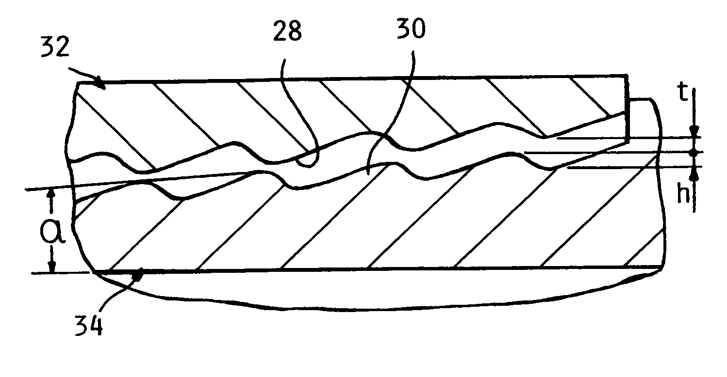
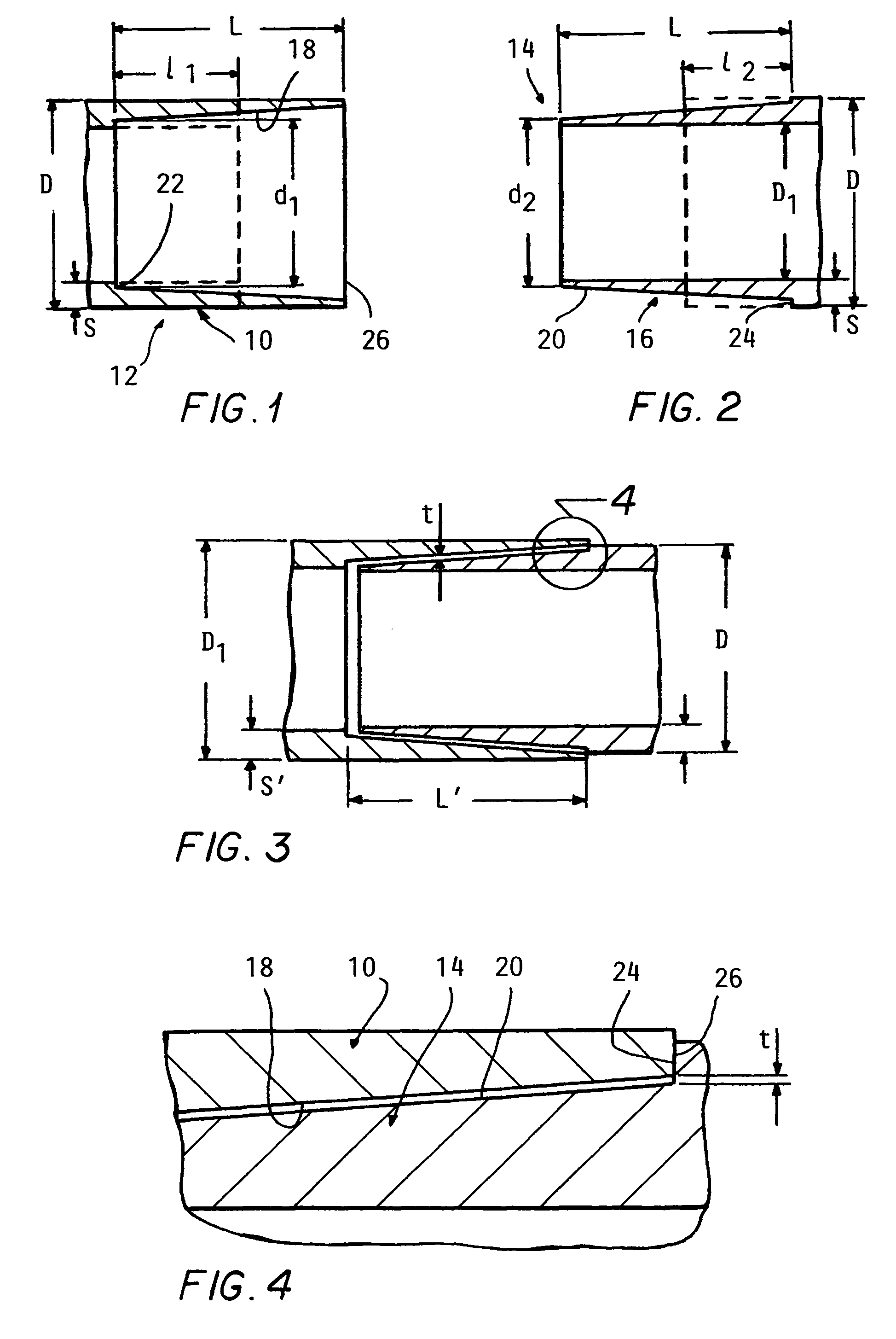
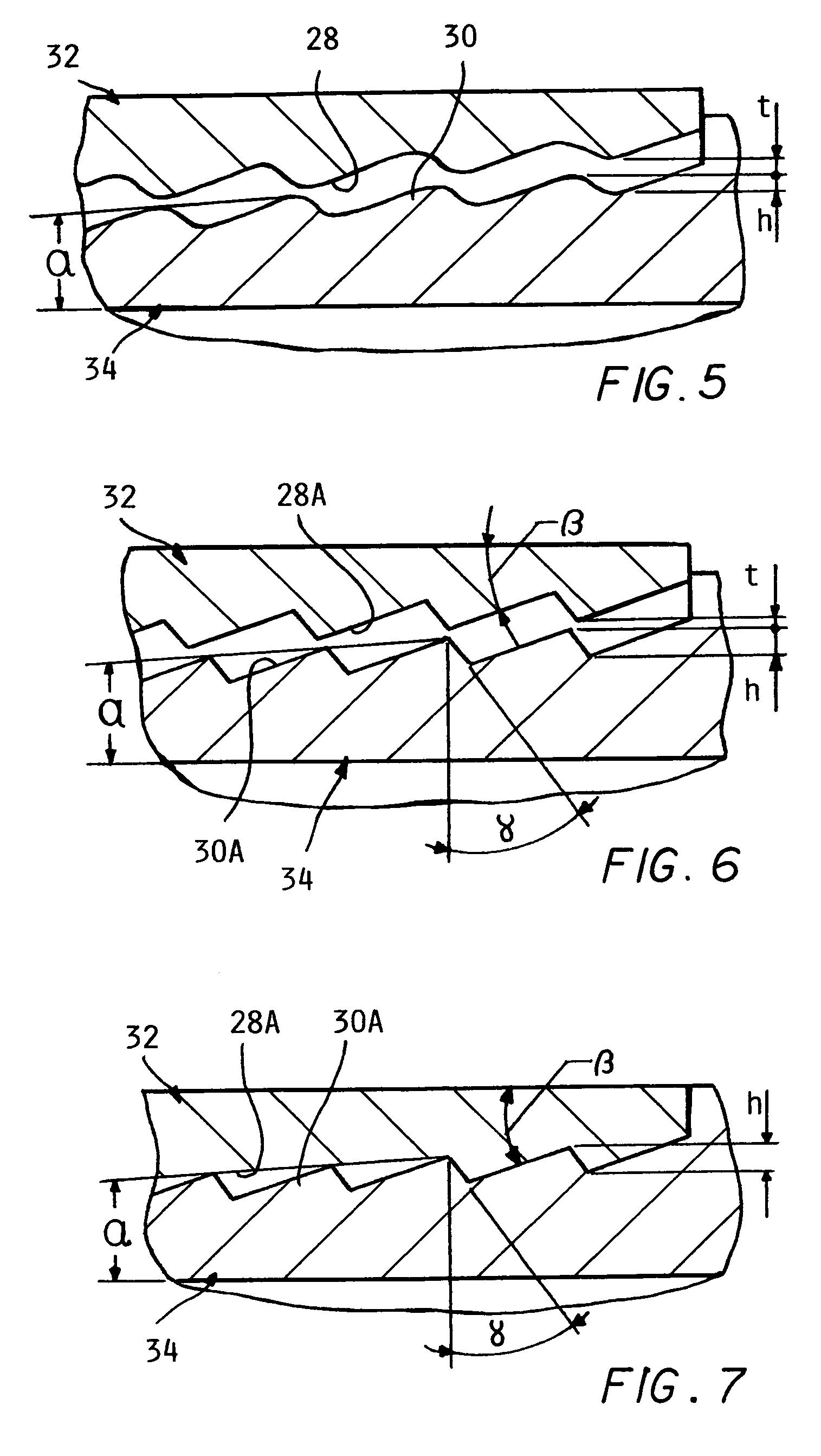
[0040]Referring to the drawings and particularly FIGS. 1-4, the inside diameter of one pipe end 10 of one pipe section 12 (FIG. 1) is formed over a length l1 into a female pipe end preferably having a tapered shape extending a length L. The outside diameter of an end 14 of another section of pipe 16 (FIG. 2) is formed along its O.D. over length l2 as by cold rolling to form a male pipe end with a preferably tapered shape 20, extending along the length L, these shapes defining complementary mating surfaces. The tapered shapes facilitates assembly of the ends and increases...


PUM

PropertyMeasurementUnit
surface angleaaaaaaaaaa
angleaaaaaaaaaa
angleaaaaaaaaaa

Abstract

A method for making pipe joints on successive pipe sections introduced into an oil well as assembled into a pipeline in which the joints are substantially of the same dimensions as the pipe sections to allow for subsequent plastic expansion of the sections. In each joint, a female pipe end is tapered on the inside and an adjacent male end is tapered on the outside preferably with a complementary self locking taper which also has an interference fit. The female pipe end is heated to be expanded sufficiently to be assembled onto the male end and thereafter cooled to grip the male end in a leakproof manner. For larger pipe sizes, the tapered shapes have features which interlock in a leakproof manner when engaged after assembly of the pipe ends. The tapered shapes preferably are formed by a reversibly positioned forming tool which is alternately engaged with male and female pipe ends to ensure perfectly matching shapes.

Description

CROSS REFERENCE TO RELATED APPLICATIONS[0001]This application claims the benefit of U.S. provisional application Ser. No. 60 / 896,287 filed on Mar. 22, 2007.BACKGROUND OF THE INVENTIONS[0002]This invention concerns pipe joining methods, and particularly the joining of pipe ends in the fabrication of various types of pipelines, primarily in well drilling and casing in the oil and gas industry and in pipelines.[0003]Pipe joints most commonly involve threaded coupling or end fittings. When deep drilling of wells, the pipe sections become progressively smaller in diameter due to the techniques which are employed for deep drilling. In order to increase flow from the wells the liners and casings are expanded in place in order to get a larger flow from the well. Threaded joints prevent getting a larger flow from the well. Threaded joints prevent mechanical expansion of the joints and create other problems. Another method for connecting tubular elements, such as pipes is known that provides ...

Claims


Application Information

Patent Timeline
Patent Type & Authority Patents(United States)
IPC IPC(8): B23P11/02B23P11/00F16B4/00
CPCB23P11/025E21B17/04F16L13/004F16L13/103F16L13/14F16L25/10F16L13/166Y10T29/49911Y10T403/48Y10T29/49865Y10T29/49913Y10T29/49936
Inventor BRAYMAN, SEMYONRUDOVICH, ALEXANDER
Owner BRAYMAN SEMYON
Why Eureka
Try Eureka