Apparatus for cooling a heat-generating member and method
a technology for cooling apparatus and heat-generating member, which is applied in the direction of electric propulsion mounting, light and heating apparatus, electric devices, etc., can solve the problems of large cooling system, critical cooling of motors, and considerable increase in the operating temperature of motors, so as to achieve efficient cooling of heat-generating members and reduce the size and weight of cooling apparatus.
- Summary
- Abstract
- Description
- Claims
- Application Information
AI Technical Summary
Benefits of technology
Problems solved by technology
Method used
Image


Examples
first embodiment
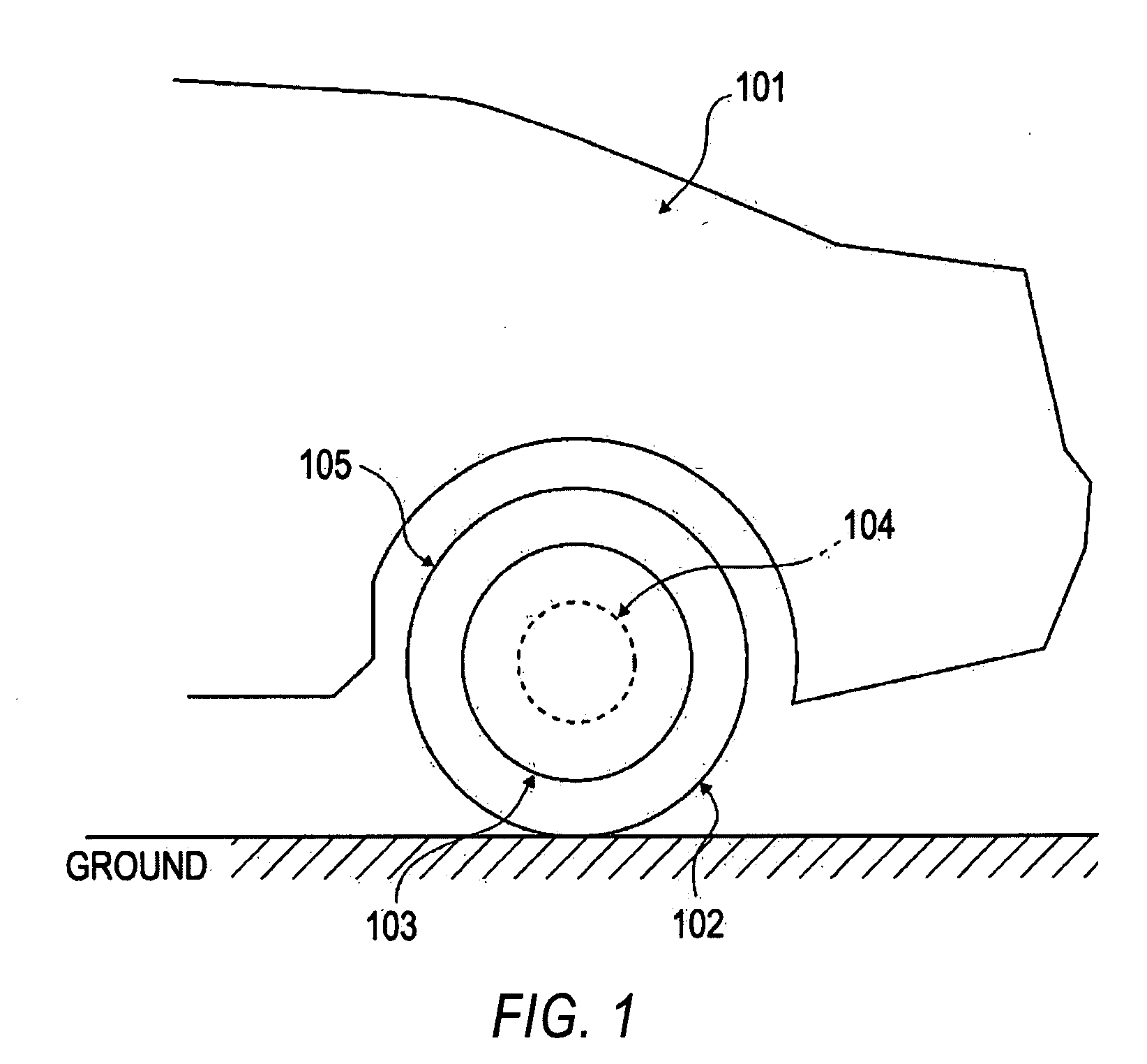
[0034]The structure of a first embodiment will be described below. FIG. 1 is a side view of a rear section of a vehicle, illustrating the manner in which an in-wheel motor that includes a cooling apparatus according to a first embodiment is mounted. FIG. 1 depicts a vehicle body 101, a tire 102, a wheel 103, an in-wheel motor 104 (in phantom), and a tire house 105.
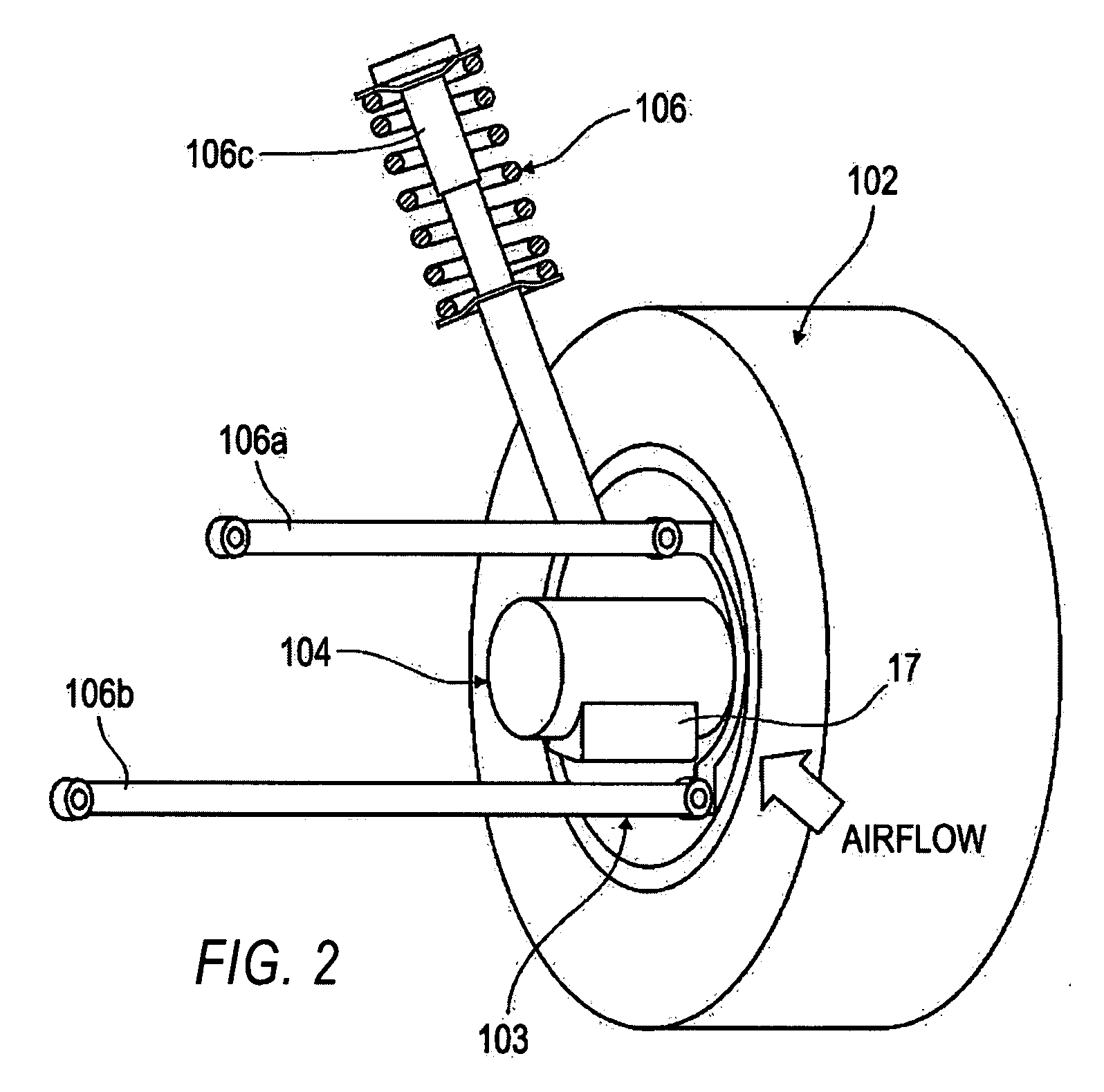
[0035]FIG. 2 is a perspective view of a suspension illustrating the manner in which the in-wheel motor 104, according to the first embodiment, attaches to the vehicle body 101. The tire 102 is connected to the vehicle body 101 by a double wishbone suspension 106 including upper and lower arms 106a and 106b and a shock absorber 106c. A housing surface of the in-wheel motor 104 (hereinafter sometimes called simply a motor) on the output side thereof is fixed to an axle (not shown). A condenser 17, which will be described below, is disposed below the in-wheel motor 104 in the generally vertical direction.
[0036]FIG. 3 is a sec...
second embodiment
[0058]The structure of a second embodiment will now be described with reference to FIG. 7. For convenience, identical elements described above in connection with the first embodiment have been given the same element numbers.
[0059]FIG. 7 is a diagram of the second embodiment of the cooling apparatus for a motor illustrating the manner in which the coolant flows therein. In the second embodiment, a reservoir tank (first reservoir tank) 21 is disposed downstream of the coolant-returning flow path 18. The reservoir tank 21 is connected to the coolant-returning flow path 9 via a coolant-returning flow path 23. In FIG. 7, liquid coolant flows in the coolant-returning flow path 23 in the direction illustrated by the arrow that is designated as a flow F11.
[0060]In the second embodiment, the reservoir tank 21 is sealed and has no atmospheric vent holes. The reservoir tank 21 is positioned below all of cooling flow paths 12a-12f when viewed from the vertical direction.
[0061]In the second embo...
third embodiment
[0067]The structure of a third embodiment of a cooling apparatus for a motor 104 will now be described in connection with FIG. 8. For convenience, identical elements described above in connection with the first and second embodiments have been given the same element numbers.
[0068]FIG. 8 is a diagram illustrating the manner in which coolant flows in the third embodiment of the cooling apparatus for a motor 104. The structure of the third embodiment differs from the structure of the second embodiment shown in FIG. 7 in that an atmospheric vent hole 22 is formed in a reservoir tank 21. Moreover, in one embodiment it is preferred that the reservoir tank 21 has a capacity that may accommodate all of the coolant in the cooling apparatus.
[0069]According to the third embodiment, the atmospheric vent hole 22 serves to suppress pressure variation. In the third embodiment, because the atmospheric vent hole 22 is formed in the reservoir tank 21, pressure variation in the coolant-returning flow ...
PUM
 Abstract
Description
Claims
Application Information
 - Generate Ideas
- Intellectual Property
- Life Sciences
- Materials
- Tech Scout
- Unparalleled Data Quality
- Higher Quality Content
- 60% Fewer Hallucinations
Browse by: Latest US Patents, China's latest patents, Technical Efficacy Thesaurus, Application Domain, Technology Topic, Popular Technical Reports.
© 2025 PatSnap. All rights reserved.Legal|Privacy policy|Modern Slavery Act Transparency Statement|Sitemap|About US| Contact US: help@patsnap.com