Flashable rooftop solar collector enclosure

a solar collector and solar energy technology, applied in the field of solar collector enclosures, can solve the problems of not much recent development in residential solar collector design, limited availability of cost-effective technology, and inability to meet the needs of residential and commercial use, and achieve the effect of convenient opening and optimal performance of the enclosed collector

Inactive Publication Date: 2007-08-30
SOUCY PAUL B
View PDF30 Cites 50 Cited by
  • Summary
  • Abstract
  • Description
  • Claims
  • Application Information

AI Technical Summary

Benefits of technology

[0009]The second part is a glazed and fully skirted top component sized for easy placement on and over the base component with a significant overlap of its skirting down over the wall of the base component and flashing. The top is then secured to the base unit so as to hold the top in a sealing manner to the base component, forming a secure, effective and weather-proof enclosure, flush mounted and flashed to the roof system. The enclosure is easily opened for and during installation, and later for maintenance and repairs, for placement and access to collector components and associated wiring and / or plumbing. The glazing is transparent to a high degree to solar radiation over a wide spectrum, for optimal performance of the enclosed collector.

Problems solved by technology

Sunshine striking the earth on a typical day is estimated to be sufficient to heat millions of homes, potentially conserving substantial fossil fuel and corresponding costs.
In the context of the exploding technology of home and building construction materials, designs and building techniques, there has not been much recent development in residential solar collector design.
Although solar energy is abundant, harnessing it for residential and commercial use is limited by available, cost effective technology.
Numerous active and passive solar collector systems for residential, commercial and industrial applications have been designed, installed and otherwise proposed; however, widespread acceptance of past solar collector systems is restricted by high initial cost, installation and weather related performance deficiencies, sometimes complicated operating nuances, unexpected maintenance issues, and high repair costs.
Costly suitable solar collection materials and fabrication techniques, unattractive installations, and questionable reliability / repair capability make their purchase unattractive to many potential users.
Other problems associated with current solar energy collectors include their being difficult, expensive or impractical for fitting or retrofitting to existing structures; bulkiness, weight, size and unaesthetic appearance; unsuitability for on-site assembly and installation by building contractors and the do-it-yourself handyperson; the requirement of a thermal mass, complicated circulation equipment and other accessories for operation; compromising of conventional roof structures and coverings; inflexibility for heating selected spaces; requirements for a single or possibly multiple glazings, thick insulating materials, rubber gaskets and other heat loss reduction materials.
The typical collector is large, bulky, difficult to manufacture, unsuitable for site assembly, difficult to install and thereby increases overall system cost.
Many years of experience have indicated that these problems are a significant contributor to the relatively low level of acceptance.
Unitary collector modules with their single or double glazed panes and insulated bodies are heavy, difficult or not suitable or intended to flash to a roof top or other support surface, as well as time consuming and difficult to access for repairs.
Placing collector modules in banks or arrays in close proximity adds complexity to the installation and in particular to access for repairs.
These problems can lead to a breach of system or roof top integrity, or damage to the internal components, or abandonment and replacement of otherwise functional collectors when simple repairs are needed or attempted.
Completed repairs where complex disassembly and reassembly is required, may result in a failure to fully restore the solar energy collection system to its original capability.

Method used


Image

  • Flashable rooftop solar collector enclosure
  • Flashable rooftop solar collector enclosure
  • Flashable rooftop solar collector enclosure

Examples


Embodiment Construction

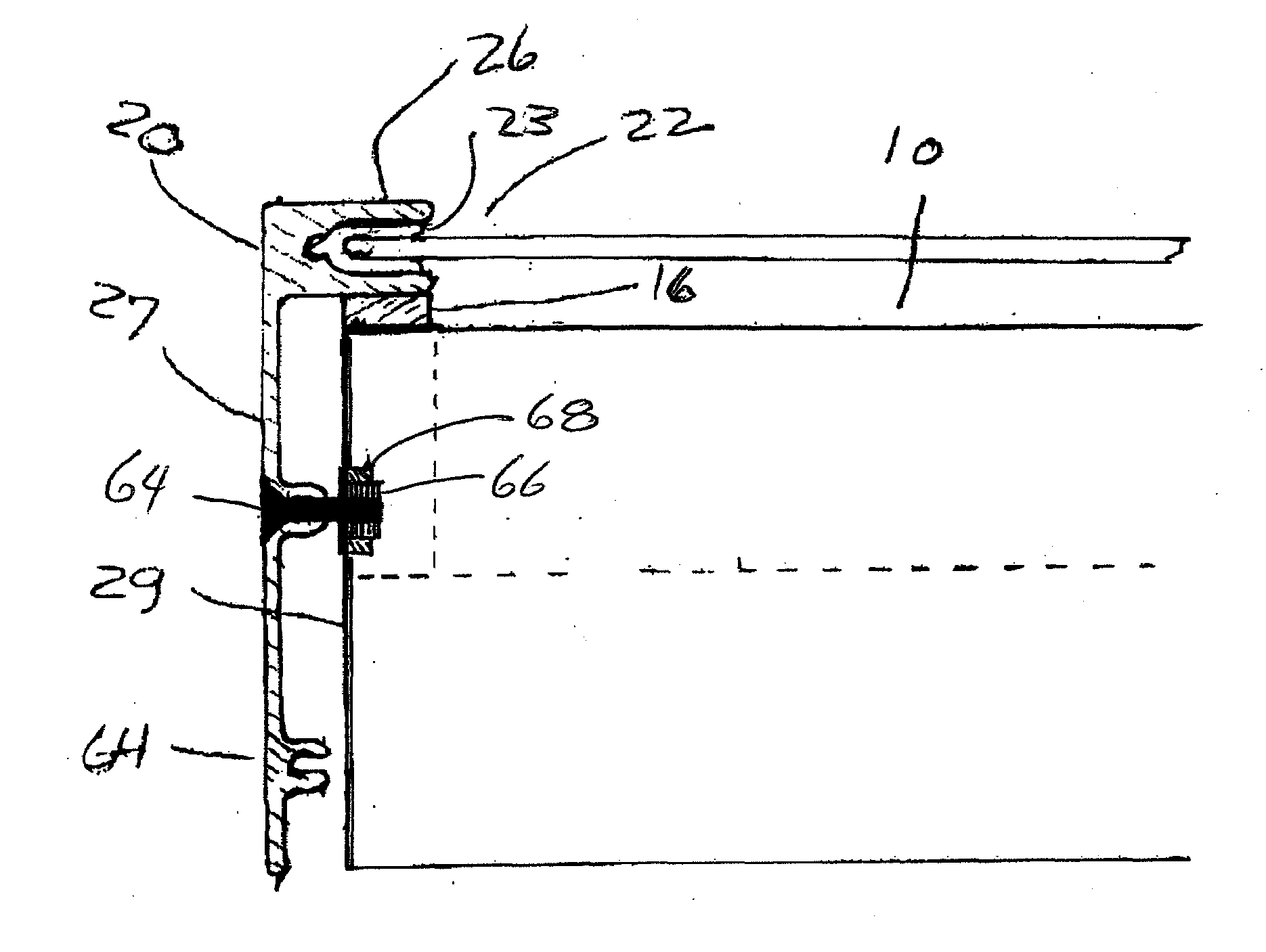
[0035]Solar collectors for heating systems typically use an energy transfer medium of gas, fluid or electricity, and may use a combination of mediums. The embodiments described below are generally presented in the context of fluid medium solar collectors but are applicable to collectors using other energy transfer mediums as well to solar power system employing photovoltaic cells and arrays. Please note, for purposes of the description that follows, the term “solar collector” extends, where the context admits, to some embodiments of the solar collector “enclosure” of the invention, particularly in solar heating applications where the primary energy capture mechanism is the circulating of air through the enclosure as a plenum, or of air or liquid through an energy absorbing conduit within the enclosure, for solar warming of the air or liquid as part of a heating circuit extending to a heat exchanger or space intended to be heated.

[0036]Solar collection systems require means for routi...


PUM


Abstract

A flashable, rooftop enclosure with a solar radiation transmissive glazing suitable for holding solar energy collector of a solar power system includes an insulated base section with sidewalls which is secured to the roof sheathing and flashed all around, and a removably attachable glazed top section with full skirt, that is secured to and over the base unit after the interior components and connections are made, so as to seal the enclosure, overlap the flashing, and admit solar radiation. The internal components may include any or all of photovoltaic and thermal converters, with electrical and thermal fluid means of removing energy from the enclosure to respective energy distribution systems.

Description

PRIORITY CLAIM[0001]This application claims priority to pending U.S. application Ser. No. 60 / 776,519 filed Feb. 24, 2006.FIELD OF THE INVENTION[0002]The invention relates to solar collector enclosures, and more particularly, to a flush mounted and flashable, two part, solar collector enclosure system that facilitates installation, maintenance and repair of solar passive, photovoltaic, and hybrid solar power systems.BACKGROUND OF THE INVENTION[0003]Solar energy is universally available. Sunshine striking the earth on a typical day is estimated to be sufficient to heat millions of homes, potentially conserving substantial fossil fuel and corresponding costs.[0004]In the context of the exploding technology of home and building construction materials, designs and building techniques, there has not been much recent development in residential solar collector design. Although solar energy is abundant, harnessing it for residential and commercial use is limited by available, cost effective ...

Claims


Application Information

Patent Timeline
Patent Type & Authority Applications(United States)
IPC IPC(8): F24J2/46
CPCF24J2/464F24J2/4647Y02E10/40Y02B10/20F24J2/465F24S80/30F24S80/40F24S80/70
Inventor SOUCY, PAUL B.
Owner SOUCY PAUL B
Why Eureka
Try Eureka