Turbocharger turbine and shaft assembly

a technology of turbine and shaft, which is applied in the direction of blade accessories, machines/engines, metal-working apparatuses, etc., can solve the problems of affecting the efficiency of the turbine, and the inability to meet the requirements of the turbin

Inactive Publication Date: 2007-08-30
CATERPILLAR INC
View PDF14 Cites 27 Cited by
  • Summary
  • Abstract
  • Description
  • Claims
  • Application Information

AI Technical Summary

Problems solved by technology

Because turbocharger components may be subject to relatively high mechanical stresses, the turbine and shaft must be produced from high-strength materials.
However, the use of titanium-aluminide can complicate joining of the turbine to the turbocharger shaft, which is often made with steel.
Titanium-aluminide and steel may have different thermal expansion properties and may produce undesirable phase transformations at their material interfaces.
Therefore, when used for applications that experience significant temperature variations, such as turbocharger components, titanium-aluminide and steel may be unsuitable for joining directly to one another.
Therefore, although the method of the '086 patent may provide a suitable connection between the turbine and shaft, two welds must be made and an additional material must be used, which can add significant time and cost to production.

Method used


Image

  • Turbocharger turbine and shaft assembly
  • Turbocharger turbine and shaft assembly

Examples


Embodiment Construction

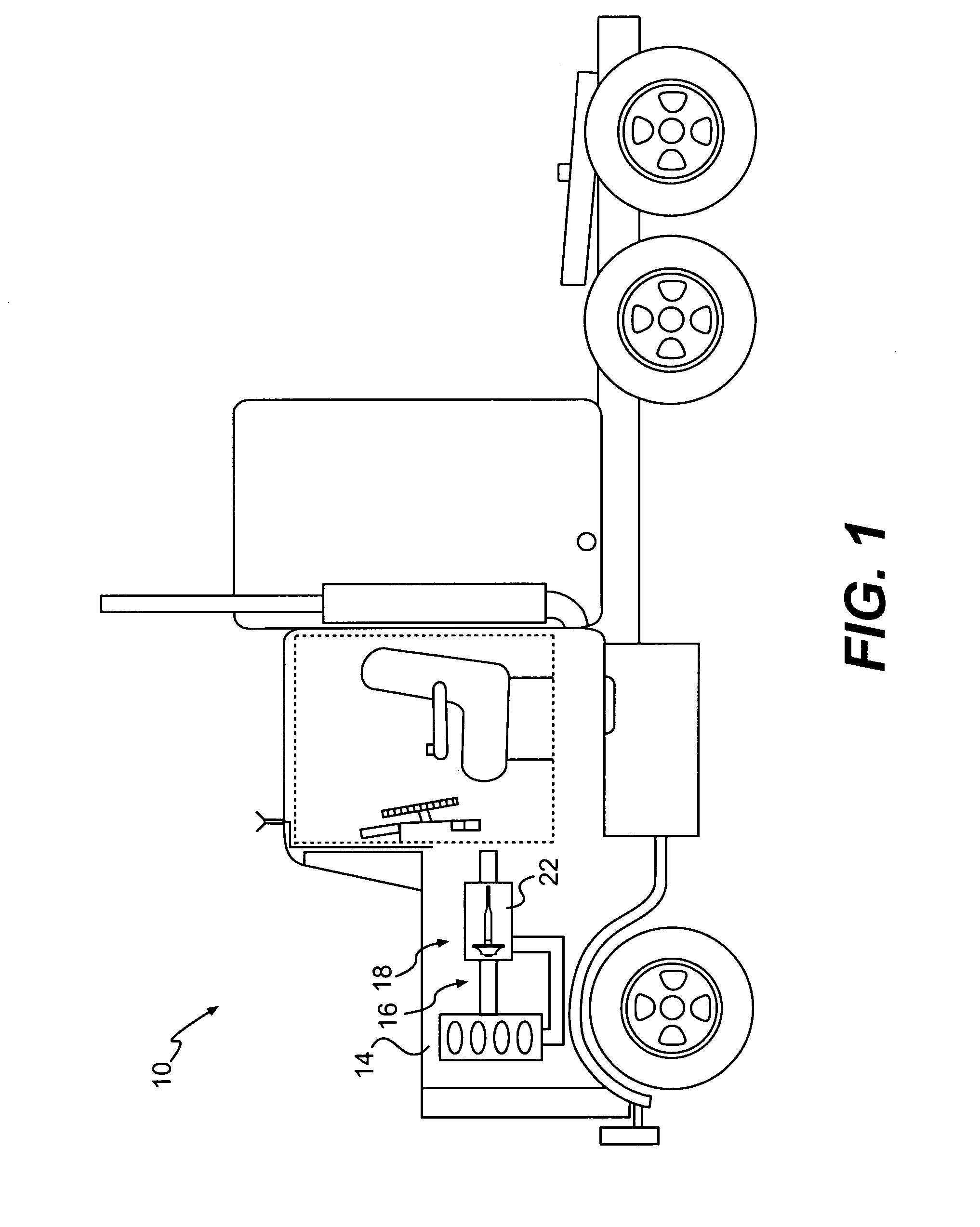
[0014]FIG. 1 illustrates a machine 10 including a turbocharger 18 according to an exemplary disclosed embodiment. As shown, machine 10 includes a power source 14 and exhaust system 16. Power source 14 may include any suitable engine type, including a diesel engine or gasoline engine. Power source 14 may be configured to supply an exhaust gas stream to exhaust system 16. As shown, machine 10 includes a highway truck. However, machine 10 may include any machine having an engine and turbocharger. For example, such machines may include off-highway trucks, trains, earth movers, boats, and / or any other machine that includes one or more turbochargers.

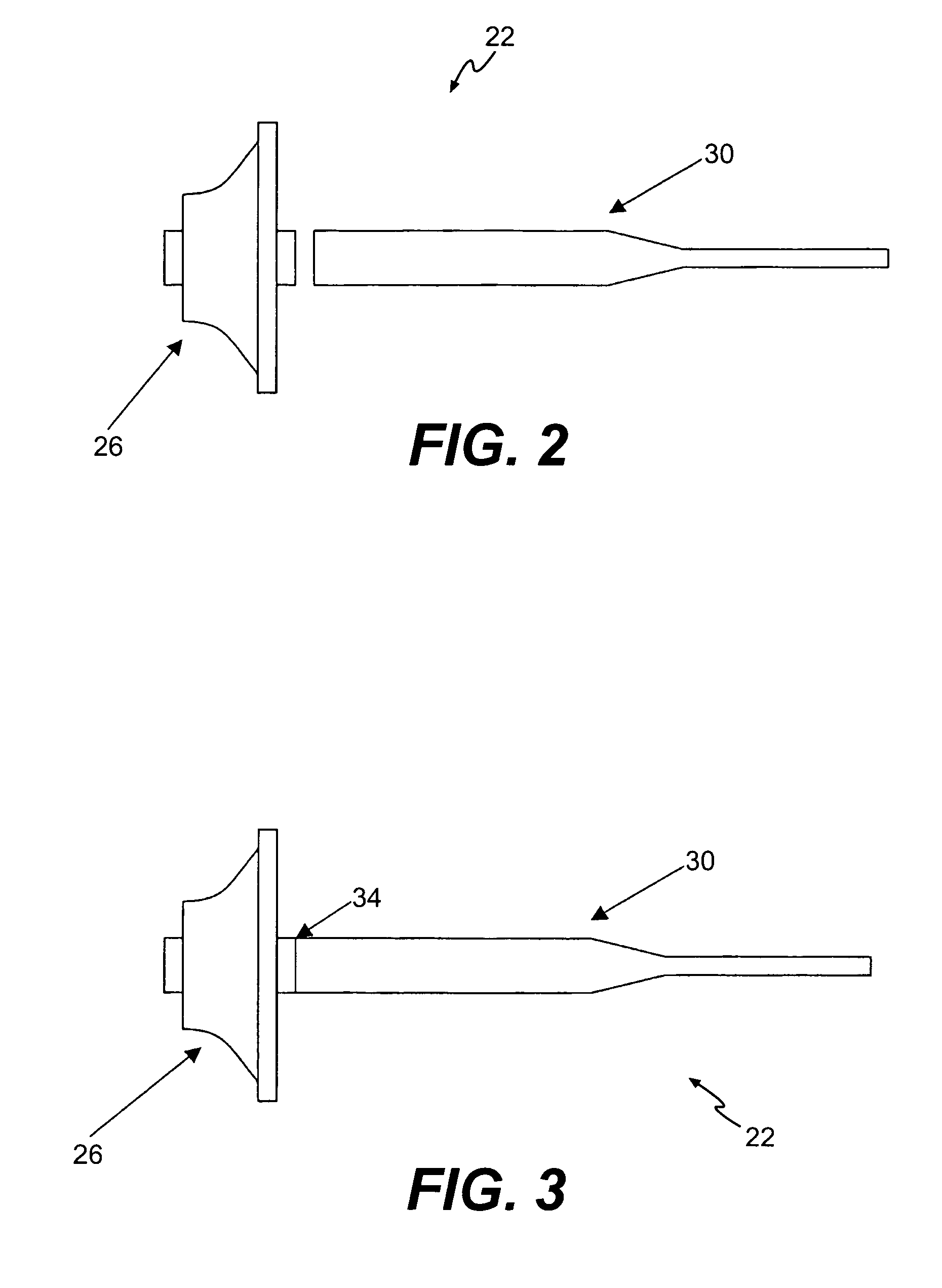
[0015] Turbocharger 18 may be positioned downstream of engine 14 and may be configured to increase the amount of air flowing into the cylinders of engine 14, thereby increasing the power output of engine 14. Turbocharger 18 may include a turbine and shaft assembly 22. As described below, turbine and shaft assembly 22 may include a turbine 26,...


PUM

PropertyMeasurementUnit
temperatureaaaaaaaaaa
timeaaaaaaaaaa

Abstract

The present disclosure includes a turbocharger. The turbocharger may include a titanium-aluminide turbine and a shaft. A single joint connects the turbine to the shaft. The joint may include an alloy comprising at least 80 atomic percent nickel and palladium.

Description

U.S. GOVERNMENT RIGHTS [0001] This invention was made with government support under the terms of Contract No. DE-AC05-000R22725 awarded by the Department of Energy. The government may have certain rights in this invention.TECHNICAL FIELD [0002] This disclosure pertains generally to turbochargers for engines, and more particularly, to methods for fabricating turbine and shaft assemblies for turbochargers. BACKGROUND [0003] Turbochargers can be used to control the power output of an engine by providing additional air to the engine cylinders. Generally, a turbocharger may include an exhaust gas driven turbine connected to a rigid shaft. Rotation of the turbine will transmit mechanical energy through the shaft to drive a compressor, which will in turn force additional air into the engine cylinders. Because turbocharger components may be subject to relatively high mechanical stresses, the turbine and shaft must be produced from high-strength materials. Further, the turbine and shaft may ...

Claims


Application Information

Patent Timeline
Patent Type & Authority Applications(United States)
IPC IPC(8): A47J36/02
CPCF16D1/027F05D2300/212B23K1/0018B23K1/002B23K1/19B23K35/3033B23K35/322B23K2201/001B23K2203/18B23K2203/24C21D1/42C21D9/50C22C19/00C22C19/03C22F1/10F01D5/025F02C6/12F05C2201/0466F05D2220/40F05D2240/60F05D2230/237F16D1/068B23K2101/001B23K2103/18B23K2103/24Y02P10/25
Inventor POLLARD, MICHAELO'HARA, STEPHEN JOHN
Owner CATERPILLAR INC
Why Eureka
Try Eureka