Phosphor and light emitting device using the same

a technology of light emitting device and phosphor, which is applied in the direction of discharge tube/lamp details, electric discharge tube, luminescent composition, etc., can solve the problems of low light emission efficiency, low weatherability of phosphor, and insufficient use of phosphors emitting yellow or green light currently available, so as to achieve high light emission efficiency, high weatherability, and high brightness

Active Publication Date: 2007-08-30
NICHIA CORP
View PDF12 Cites 26 Cited by
  • Summary
  • Abstract
  • Description
  • Claims
  • Application Information

AI Technical Summary

Benefits of technology

[0014] The present invention, with the constitution described above, is capable of providing a phosphor which emits light of high brigh

Problems solved by technology

However, such phosphor has low weatherability and low light emission efficiency.
However, the phosphors emitting yellow or green light currently available do not have sufficiently high efficiency of emission for use in light emitting devices including the applications to display and illumination, and it is called for to

Method used


Image

  • Phosphor and light emitting device using the same
  • Phosphor and light emitting device using the same
  • Phosphor and light emitting device using the same

Examples


embodiments

(Phosphor)

[0020] One embodiment of the phosphors of the present invention has the composition represented by the following general formula:

(M11−yRy)aMgM2bM3cOa+2b+(3 / 2)cX2

wherein M1 is at least one element selected from the group consisting of Ca, Sr, Ba, Zn and Mn, M2 is at least one element selected from the group consisting of Si, Ge and Sn, M3 is at least one element selected from the group consisting of B, Al, Ga and In, X is at least one element selected from the group consisting of F, Cl, Br and I, R is at least one element selected from the group consisting of rare earth elements with Eu being inevitable element, and y, a, b and c satisfy the following relationships of 0.0001≦y≦0.3, 7.0≦a<10.0, 3.0≦b<5.0 and 0≦c<1.0.

[0021] The phosphor includes at least one element selected from the group consisting of Ca, Sr, Ba, Zn and Mn. Preferably, the phosphor includes Ca, while a portion of Ca may be substituted with at least one of Mn, Sr and Ba.

[0022] The phosphor includes at l...

examples

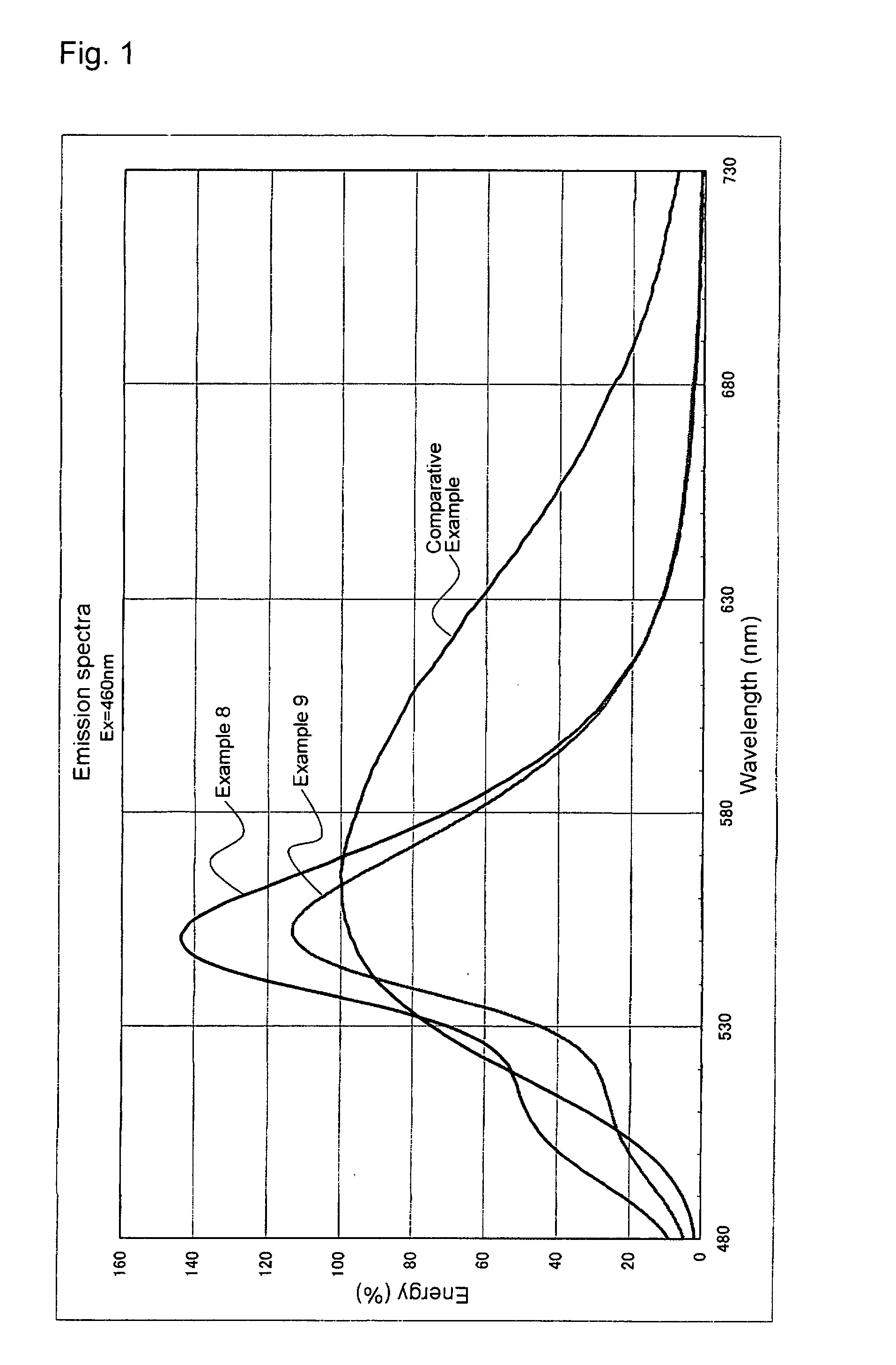
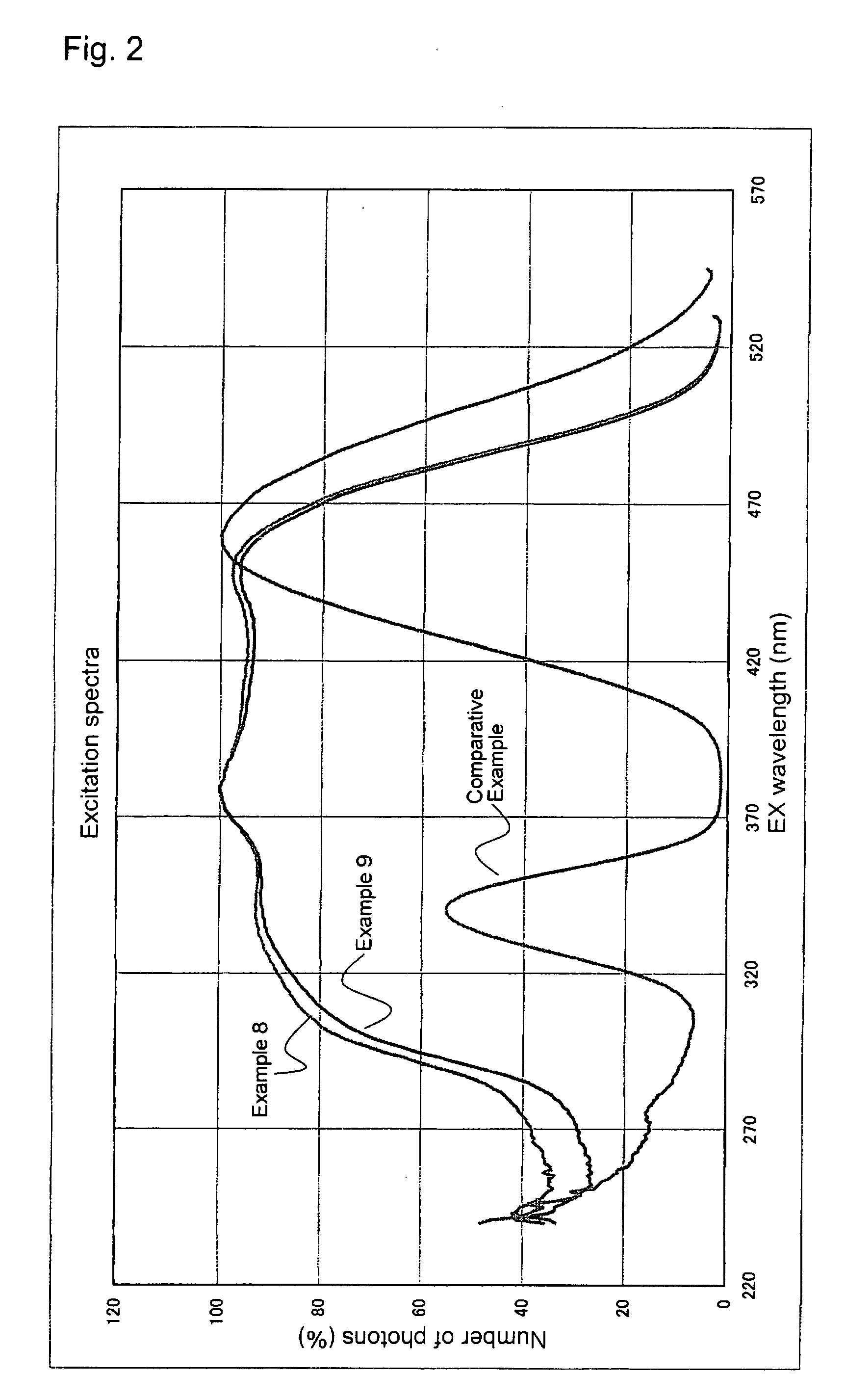
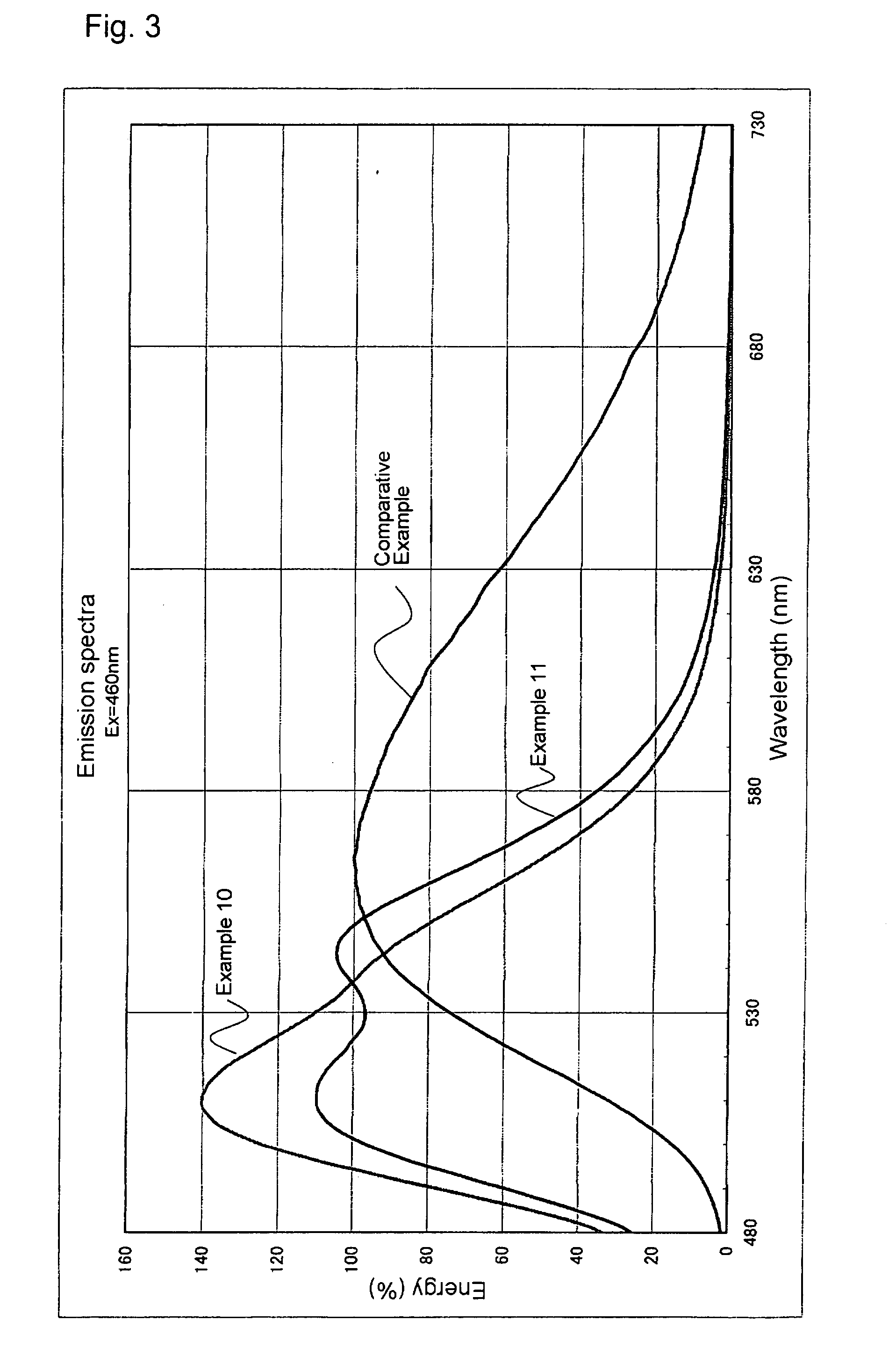
[0052] The present invention will now be described by way of Examples. FIG. 1 shows emission spectra of Examples 8 and 9. FIG. 2 shows excitation spectra of Examples 8 and 9. FIG. 3 shows emission spectra of Examples 10 and 11. FIG. 4 shows emission spectra of Examples 24 and 29. It is noted that considering evaporations of alkaline earth metal elements such as Ca and the like during the firing step in the manufacturing process, the amount(s) of the alkaline earth metal element(s) used to be mixed as raw material(s) are larger than those of such element(s) in final products having the intended compositions.

examples 1 to 5

[0053] In example 1, the raw materials are mixed to finally produce a composition of Ca8.475Eu0.025MgSi4O16Cl2 (i.e. intended composition). Examples 2 to 5 relate to compositions in which amounts of Ca and Eu are arranged so that the total amount of Ca and Eu is 8.500 mols. Specifically, Example 2 relates to a phosphor having the composition of Ca8.450Eu0.050MgSi4O16Cl2. Example 3 relates to a phosphor having the composition of Ca8.425Eu0.075MgSi4O16Cl2. Example 4 relates to a phosphor having the composition of Ca8.350Eu0.150MgSi4O16Cl2. Example 5 relates to a phosphor having the composition of Ca8.250Eu0.250MgSi4O16Cl2.

[0054] Examples 2 to 33 are manufactured by methods almost the same as the method in Example 1, and therefore description thereof may partly be omitted.

[0055] In Example 1, CaCO3, Eu2O3, MgCO3, SiO2 and CaCl2 are used as the raw materials. CaCO3, Eu2O3, MgCO3, SiO2 and CaCl2 are weighed out so that a molar ratio of the elements becomes Ca:Eu:Mg:Si:Cl=8.475:0.025:1:...


PUM


Abstract

There is provided a phosphor emitting light of high brightness and having high weatherability, which has a composition represented by the following general formula:
(M11−yRy)aMgM2bM3cOa+2b+(3/2)cX2
wherein M1 is at least one element selected from the group consisting of Ca, Sr, Ba, Zn and Mn, M2 is at least one element selected from the group consisting of Si, Ge and Sn, M3 is at least one element selected from the group consisting of B, Al, Ga and In, X is at least one element selected from the group consisting of F, Cl, Br and I, R is at least one element selected from the group consisting of rare earth elements with Eu being an inevitable element, and y, a, b and c satisfy the following relationships of 0.0001≦y≦0.3, 7.0≦a<10.0, 3.0≦b<5.0 and 0≦c<1.0.

Description

BACKGROUND OF THE INVENTION [0001] 1. Field of the Invention [0002] The present invention relates to a phosphor and a light emitting device using the same. The light emitting device is used in signal lights, illumination apparatuses, displays, indicators and the like. [0003] 2. Description of the Related Art [0004] Light emitting devices constituted from a combination of a light source and a phosphor which emits light when excited by light from the light source has been widely known hitherto. These light emitting devices include one that combines a light source emitting light in a region ranging from near-ultraviolet rays to visible light of shorter wavelengths and a phosphor which emits light when excited by the light from the light source. This type of light emitting device uses a phosphor having a composition of, for example, ZnS:Cu, (Sr, Ca)Ga2S4:Eu or SrAl2O4:Eu. However, such phosphor has low weatherability and low light emission efficiency. Thus there is a demand for phosphor...

Claims


Application Information

Patent Timeline
IPC IPC(8): C09K11/08C09K11/61C09K11/66
CPCC09K11/7721C09K11/7734C09K11/7764C09K11/7758C09K11/7749C09K11/77342
Inventor MURAZAKI, YOSHINORI
Owner NICHIA CORP
Why Eureka
Try Eureka