
Charge sharing method and apparatus for display panel

a display panel and charging method technology, applied in the direction of instruments, static indicating devices, etc., can solve the problems of poor power-saving function and inability to neutralize all together the charges of the display panel b>140/b>, and achieve the effect of optimizing the power-saving function

Inactive Publication Date: 2007-08-30
CHUNGHWA PICTURE TUBES LTD
View PDF3 Cites 16 Cited by
  • Summary
  • Abstract
  • Description
  • Claims
  • Application Information

AI Technical Summary

Benefits of technology

[0010] An object of the present invention is to provide a charge-sharing method for a display panel, so as to improve the conventional charge-sharing method of controlling signals, thereby optimizing the power-saving function.
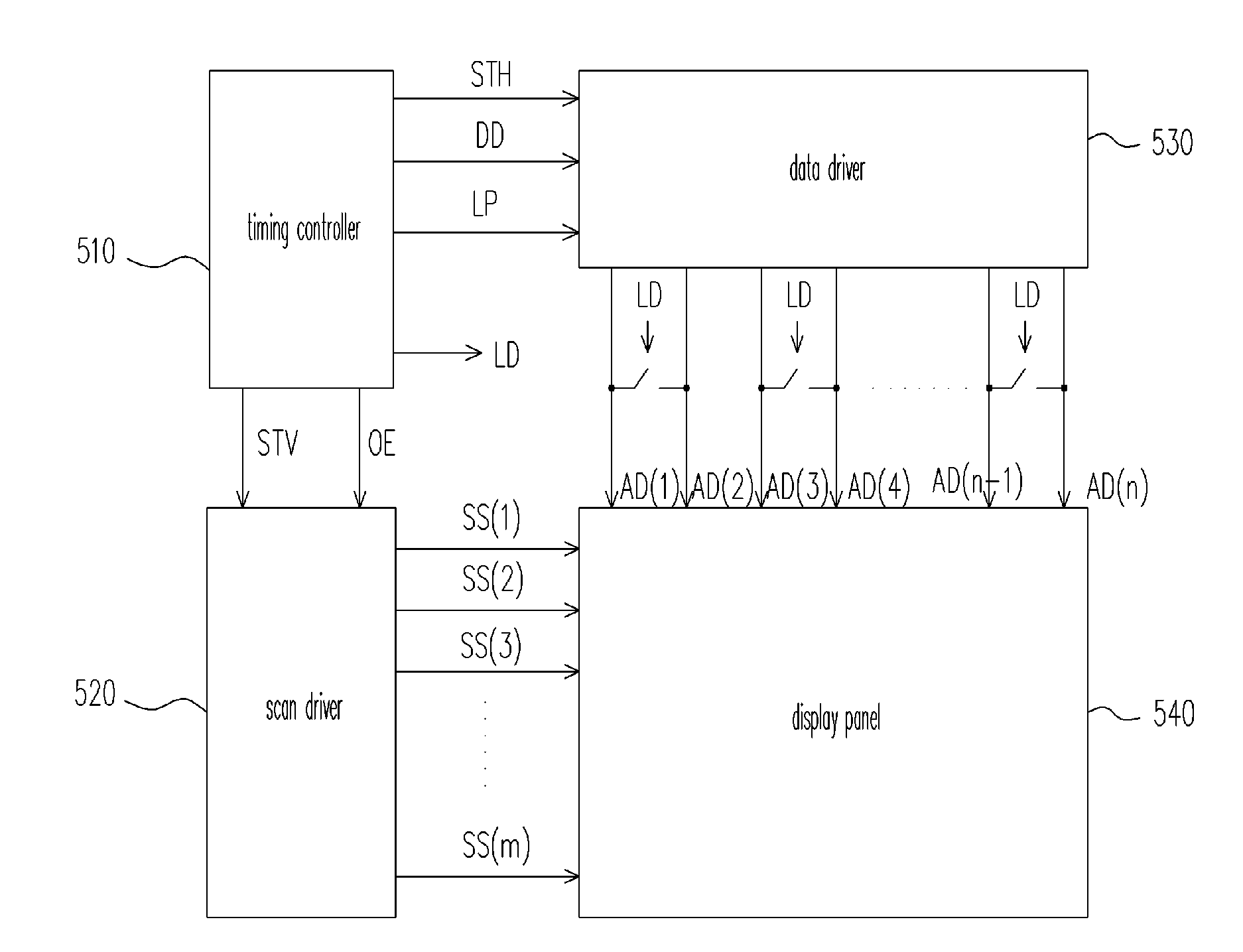
[0014] The conventional charge-sharing function is only capable of neutralizing the polarities of positive and negative charges on adjacent data lines, so that the power-saving function cannot be optimized. In the present invention, charge-sharing is completed during the period when the pixels are turned on. As a result, not only the polarities of positive and negative charges on adjacent data channels but also the polarities of positive and negative charges on adjacent odd and even pixels on the corresponding scan lines are neutralized, thus optimizing the power-save effect.

Problems solved by technology

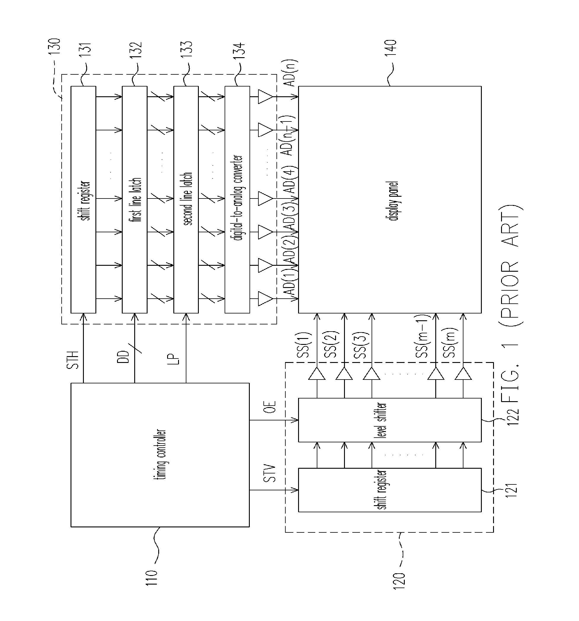
Therefore, with the conventional technology, only the polarities of positive and negative charges on adjacent odd data lines and even data lines can be neutralized, but the pixel charges in the display panel 140 cannot be neutralized all together.
Consequently, the power-saving function of the conventional charge-sharing method is poor.

Method used


Image

  • Charge sharing method and apparatus for display panel
  • Charge sharing method and apparatus for display panel
  • Charge sharing method and apparatus for display panel

Examples


Embodiment Construction

[0024]FIG. 5 depicts a block diagram of a display having a charge-sharing function according to an embodiment of the invention. The implementation of the data driver 530 and the scan driver 120 in the figure is the same as that of the data driver 130 and the scan driver 120 in FIG. 1. FIG. 6 is a timing diagram illustrating each of the signals in FIG. 5. Referring to FIGS. 5 and 6, the display panel 540 is assumed to be a thin film transistor-liquid crystal display panel (TFT-LCD panel) having n×m pixels, wherein m and n are integers.

[0025] The timing controller 510 outputs a vertical synchronization signal STV and an enabling signal OE to the scan driver 520. The scan driver 520 determines, according to the output enabling signal OE, whether to output the scan signals SS(1)-SS(m) to the scan channels of the display panel 540. Herein, the ‘period when the pixels are turned on’ refers to a period in which the enabling signal OE is at a low level (i.e., outputting the scan signals SS...


PUM


Abstract

A charge-sharing method and apparatus for display panel including at least two data channels are provided. The charge-sharing method includes the following steps. First, one data channel is connected with another data channel at a first time-point of a period during which the pixels are turned on. The connections among the data channels are turned off at a second time-point of the period during which the pixels are turned on. Thereby, the display signal can be transmitted to the data channel in the display panel.

Description

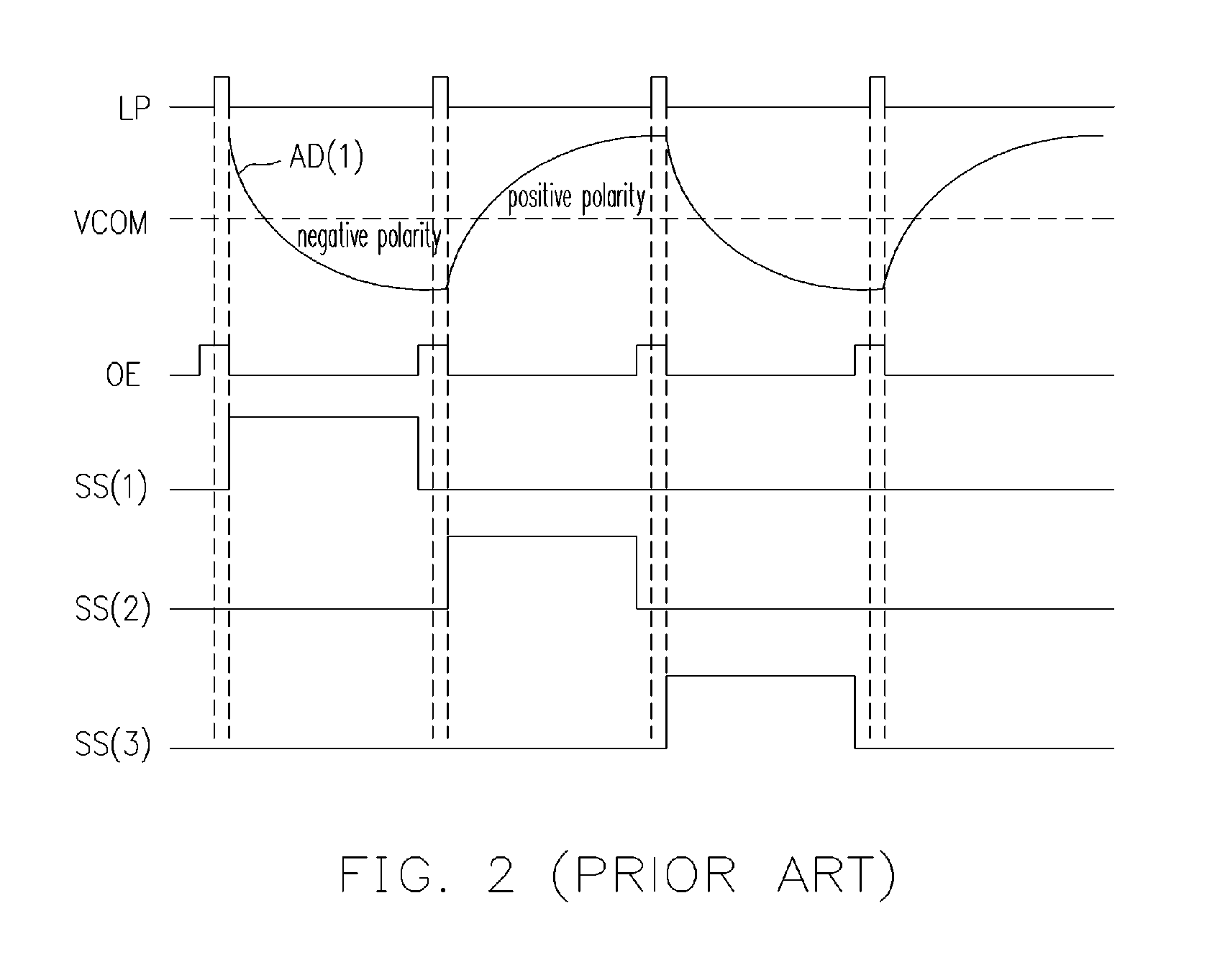
BACKGROUND OF THE INVENTION [0001] 1. Field of Invention [0002] The present invention relates to a drive for display panel, and more particular to a charge sharing method and apparatus for a display panel. [0003] 2. Description of Related Art [0004]FIG. 1 depicts a block diagram of a generic display. FIG. 2 is a timing diagram illustrating each of the signals in FIG. 1. Referring to FIGS. 1 and 2, assuming the display panel 140 is an n×m display panel, wherein m and n are integers. A timing controller 110 outputs both a vertical synchronization signal STV and an enabling signal OE to a scan driver 120. In the scan driver120, a shift register 121 is used to shift the received vertical synchronization signals STV progressively, so as to output multiple scan signals. A level shifter 122 receives the scan signals output from the shift register 121, and determines whether to output the scan signals SS(1)-SS(m) to the scan channel of display panel 140 through a buffer based on the output ...

Claims


Application Information

Patent Timeline
Patent Type & Authority Applications(United States)
IPC IPC(8): G09G3/36
CPCG09G3/3614G09G2330/023G09G2310/0251G09G3/3688
Inventor YEH, LIANG-HUA
Owner CHUNGHWA PICTURE TUBES LTD
Learn More