Contrast ratio and viewing angle improvement for a TN- LCD

a technology of applied in non-linear optics, instruments, optics, etc., can solve the problems of low contrast, narrow viewing angle, tn lcd, etc., and achieve the effect of improving both contrast ratio and viewing angle, and improving the contrast ratio of an lcd

Inactive Publication Date: 2007-08-30
KOPIN CORPORATION
View PDF10 Cites 18 Cited by
  • Summary
  • Abstract
  • Description
  • Claims
  • Application Information

AI Technical Summary

Benefits of technology

[0005] The first-type optical compensation layer, having negative birefringence, a low retardation value of, for example, between about −1 and about −50 nm and an optical axis parallel to a plane of the first substrate or the second substrate, can significantly improve the contrast ratio of an LCD at a relatively low applied voltage, for example, between about 2 volts and about 4 volts. With the combination of wide-viewing-angle compensation films, the negative birefringence optical compensation layer of the invention can improve both the contrast ratio and viewing angle of an LCD of the invention at a relatively low applied voltage. The first-type optical compensation layer employed in the invention can also improve the contrast ratio of both normal and oblique incident light. It can compensate residual (intermediate on-state between full-on- and off-states) LC birefringence, as compared to the LC birefringence in the full-on state, to thereby improve the contrast ratio, especially in LCDs operated at low voltages.
[0006] Without being bound to a particular theory, it is believed that, in the LCDs of the invention, the first-type optical compensation layer can improve normal incident and oblique angle contrast ratios (CR), and the second-type optical compensation layer can improve a normal incident and relatively-wide oblique angle contrast ratios.

Problems solved by technology

The drawbacks of these conventional TN LCDs are low contrast and narrow viewing angles (e.g., ±40° horizontally and −15° and +30° vertically).

Method used


Image

  • Contrast ratio and viewing angle improvement for a TN- LCD
  • Contrast ratio and viewing angle improvement for a TN- LCD
  • Contrast ratio and viewing angle improvement for a TN- LCD

Examples


example

Contrast Ratio Calculation to Generate Simulated Results

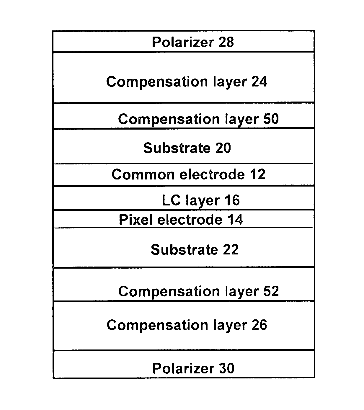
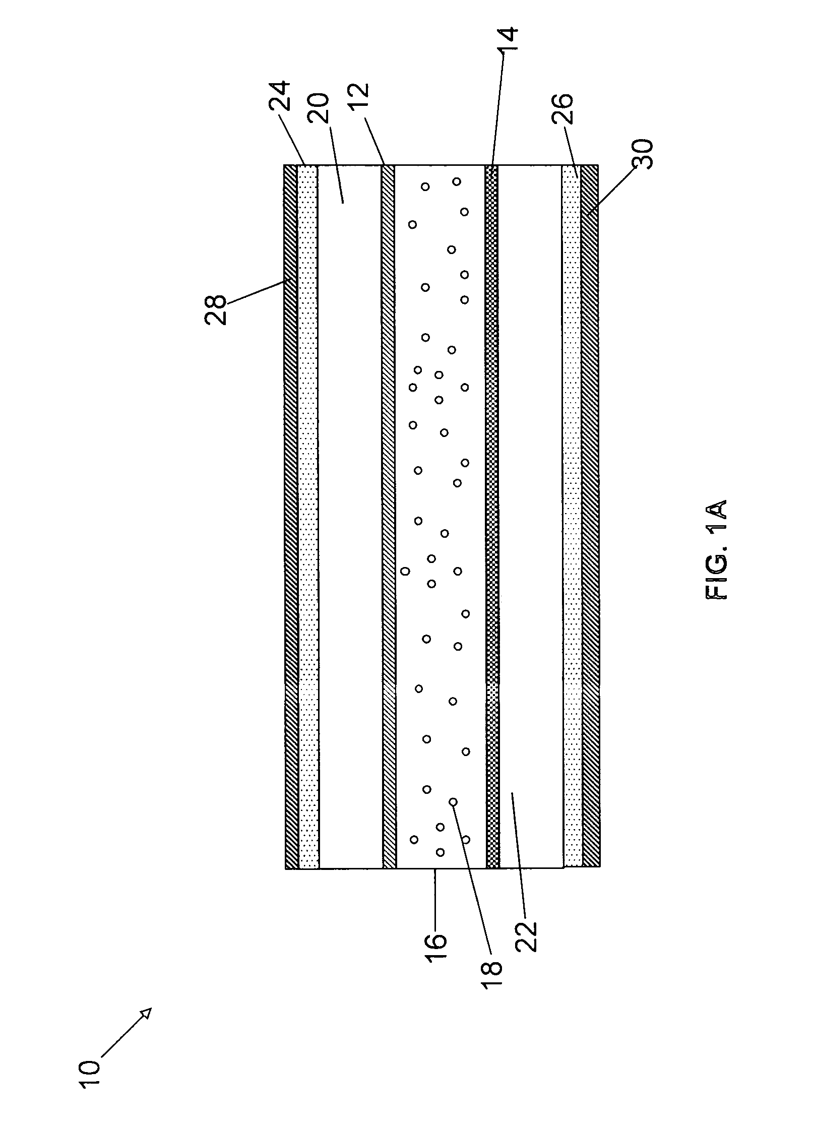
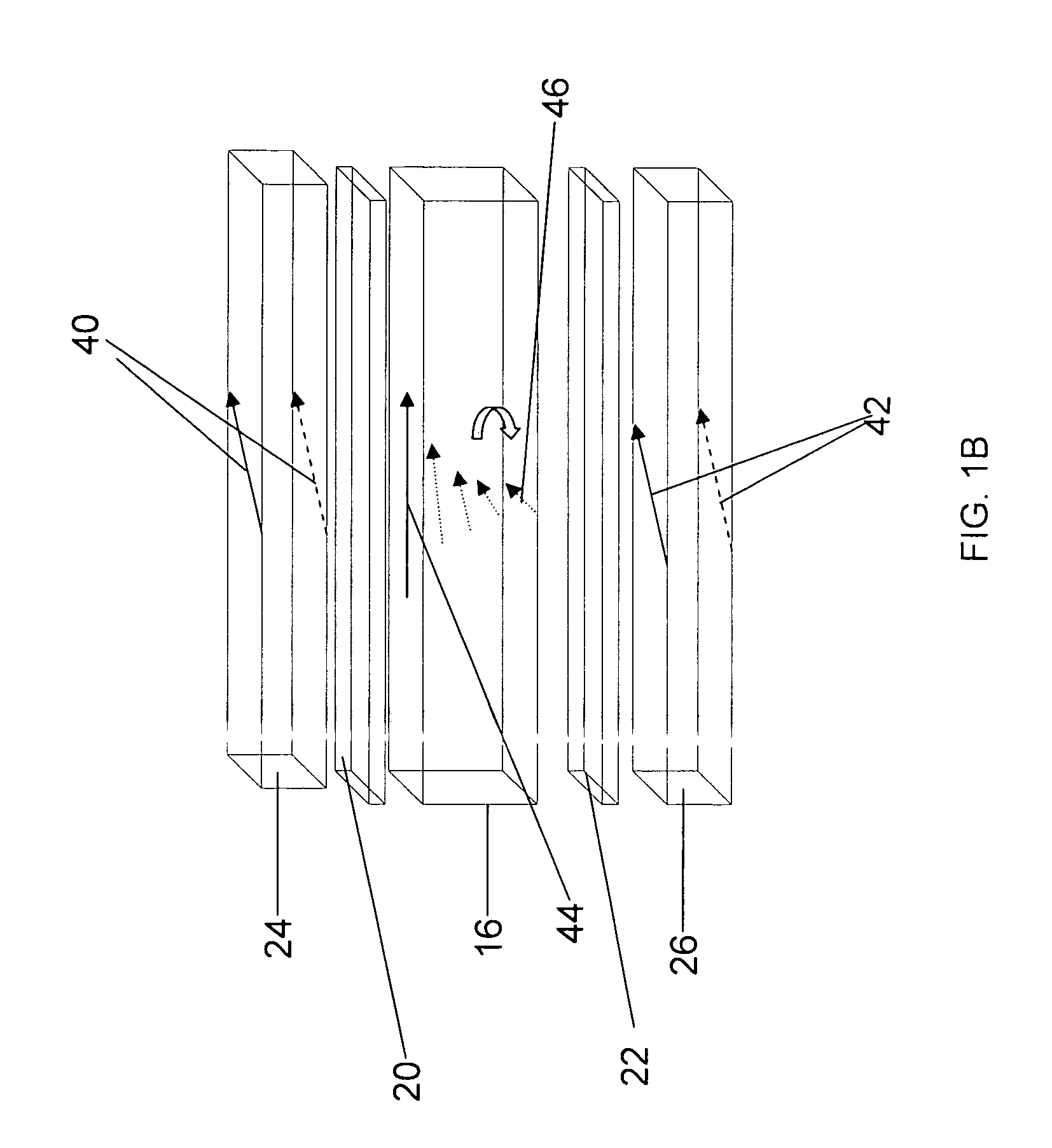
[0069] The contrast ratio of the TN LCDs of the invention can be modeled with both two-dimensional and thee-dimensional models, such as Autronic 2-D LC Modeling software (2-D modeling) and Shintech 3-D LC Modeling software (3-D modeling). Geometrical optics approximation can be used for such modeling to make a fast estimation on the TN LCD electrical optical transmission. The contrast ratio improvement of the LCDs of the invention can arise from the shift of the contrast ratio peak from off-normal incidence to close to normal incidence, without or minimal loss of contrast ratio peak.

[0070] A standard 90-degree TN cell with a cell gap of 2.2 μm and LC ZOC-5057LA available from Chisso Corporation as an LC material are considered in the calculations below. The pretilt angle is 20-degrees. In the calculation, optical compensation layers 24 and 26, having no=1.51, ne=1.50, and layer thickness d=10 nm to 200 nm are considered. The...


PUM

PropertyMeasurementUnit
applied voltageaaaaaaaaaa
viewing angleaaaaaaaaaa

Abstract

A liquid crystal display includes a liquid crystal layer between a first substrate and a second substrate, at least one first-type optical compensation layer over the liquid crystal layer, and at least one polarizer layer over the first-type optical compensation layer. The liquid crystal layer has a birefringence liquid crystal material. The first-type optical compensation layer includes a negative birefringence material. The optical axis of the first-type optical compensation layer is substantially parallel to a plane of either of the first substrate or the second substrate throughout the the layer. A liquid crystal display is prepared by forming a liquid crystal layer as described above, forming at least one first-type optical compensation layer as described above, and forming at least one polarizer layer over the first-type optical compensation layer.

Description

RELATED APPLICATION [0001] This application claims the benefit of U.S. Provisional Application No. 60 / 755,107, filed on Dec. 29, 2005, the entire teachings of which are incorporated herein by reference.BACKGROUND OF THE INVENTION [0002] The market for liquid crystal displays (LCDs) is increasing rapidly, especially in areas of high performance LCDs and hand-held mobile device applications. These applications generally require high resolutions. high contrast levels. wide symmetrical viewing angles and fast response times. In addition, high contrast levels with respect to different viewing angles, gray-scale inversion, colorimetry and optical response of an LCD are important factors of high quality LCDs. Most conventional LCDs are 90° twisted-nematic liquid crystal displays (TN LCDs). The drawbacks of these conventional TN LCDs are low contrast and narrow viewing angles (e.g., ±40° horizontally and −15° and +30° vertically). For LCD monitor and TV applications, low applied voltage and...

Claims


Application Information

Patent Timeline
Patent Type & Authority Applications(United States)
IPC IPC(8): G02F1/1335
CPCG02F1/13363G02F2001/133531G02F2413/105G02F2413/06G02F2413/08G02F2413/04G02F1/133531
Inventor ONG, HIAP L.
Owner KOPIN CORPORATION
Why Eureka
Try Eureka