Inverter with time counting function

a technology of inverter and function, which is applied in the field of inverter, can solve the problems of increasing the cost of the inverter, the inability to display the stop time on the display device of the inverter, and the inability to identify the stop time, etc., and achieves the effect of convenient identifying the stop period, facilitating determining the time, and relatively precise methods

Inactive Publication Date: 2007-08-30
FUJI ELECTRIC CO LTD
View PDF11 Cites 4 Cited by
  • Summary
  • Abstract
  • Description
  • Claims
  • Application Information

AI Technical Summary

Benefits of technology

[0007]For obviating the problems described above, the inverter according to the invention utilizes the oscillator circuit in the inverter and counts the time from the instance at which the protector circuit starts operating due to an anomaly caused. When the installation manager finds, during a patrol and such a routine, that the inverter is conducting the protecting operation thereof, the configuration according to the invention makes it possible for the installation manager to determine the time at which the protector circuit started exhibiting the protecting function thereof, by subtracting the counted time from the present time known easily by the other means.
[0008]According to an aspect of the invention, there is provided an inverter including: a microcomputer controlling the inverter, the microcomputer including a protector circuit, the protector circuit stopping the operation of the inverter when an anomaly is caused; a counter counting the driving clock signals of the microcomputer from the instance at which the protector circuit starts operating; and a conversion circuit outputting the number of the clock signals counted by the counter. According to the invention, a relatively inexpensive but not-so-precise oscillator circuit such as an oscillator circuit in the inverter is used to count the time from the instance, at which the protector circuit starts operating. Although a certain time counting error may be caused due to the not-so-precise oscillator circuit used according to the invention, the time counting

Problems solved by technology

Although the stop time monitoring using the programmable controller ranking high does not pose any problem on the accuracy thereof, the monitoring costs soars and it is not possible to display the stop time on the display device of the inverter.
However, the costs of the inverter increases, since it is necessary for the inverter to equip the memory for storing a lot of data relevant to the anomaly caused and a processor that controls the data storage.
For simply obtaining the period from the time at which the inverter

Method used


Image

  • Inverter with time counting function
  • Inverter with time counting function
  • Inverter with time counting function

Examples


Embodiment Construction

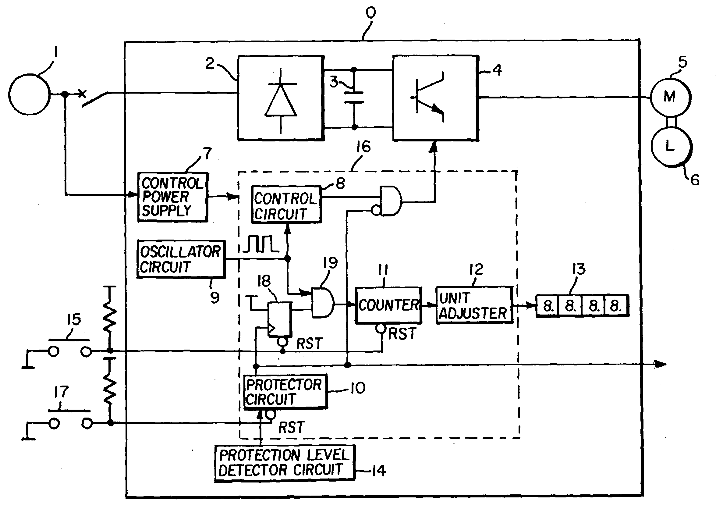
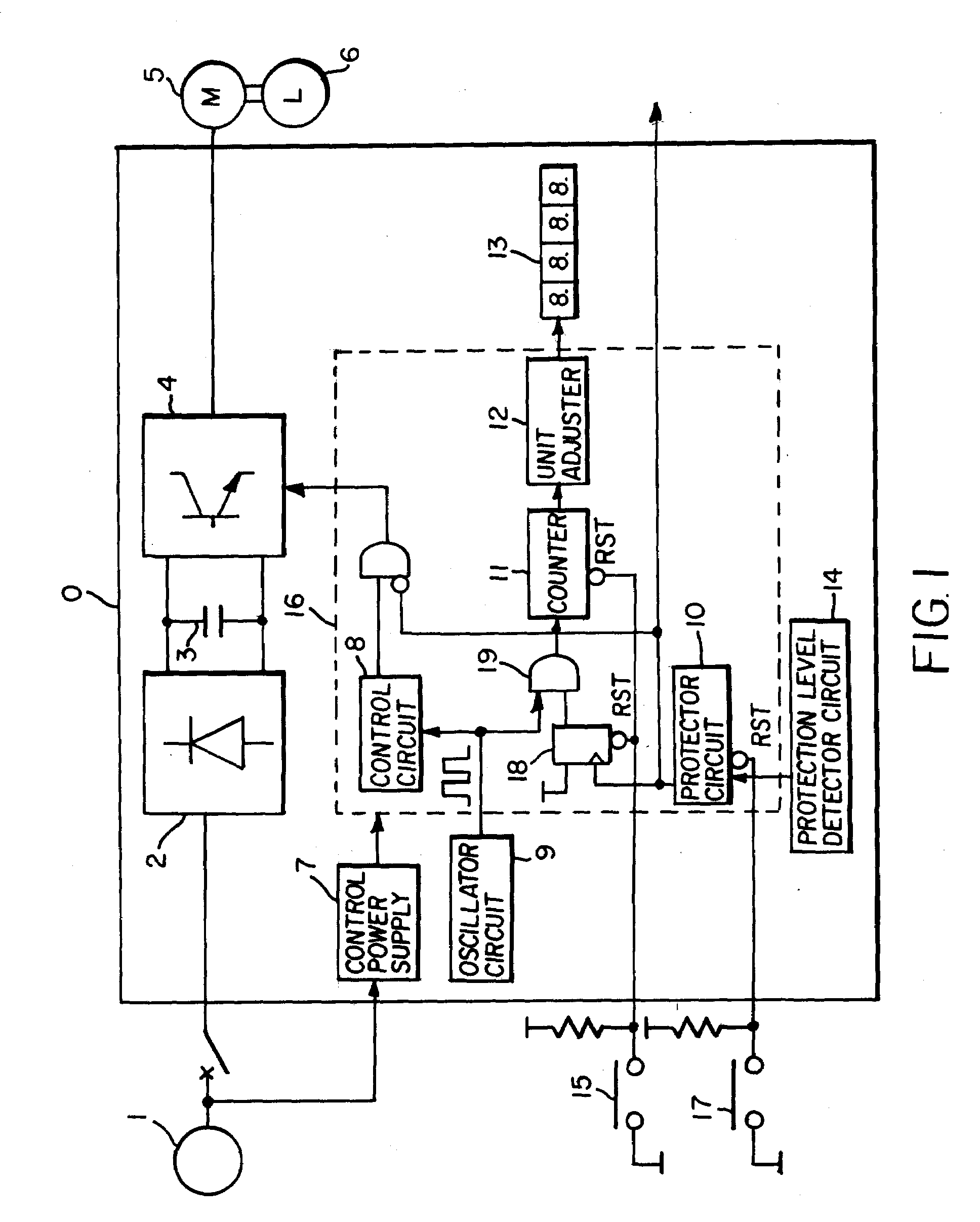
[0012]Now the invention will be described in detail hereinafter with reference to the accompanied drawings which illustrate the specific embodiments of the invention. FIG. 1 is a block diagram describing the configuration of an inverter according to a first embodiment of the invention. In FIG. 1, inverter 0, commercial AC input power supply (hereinafter referred to as “main power supply”) 1, motor 5, and load 6 are shown. Inverter 0 includes a forward converter circuit 2 that rectifies the AC fed from AC input power supply 1 to convert the AC signal to a DC signal, a capacitor 3 that smoothes the rectified output from forward converter circuit 2, and inverter circuit 4 that converts the DC to an AC modulated by PWM and having an arbitrary frequency and an arbitrary voltage within the respective predetermined ranges. Motor 5 drives load 6.

[0013]A control power supply different from main power supply 1 is connected to control power supply circuit 7. A signal for switching on and off t...


PUM


Abstract

The inverter according to the invention includes a control microcomputer including a protector circuit that stops the inverter when an anomaly is caused, a counter that counts the driving clock signals of the microcomputer from the instance at which the protector circuit starts working, and a conversion circuit that converts the clock signals counted by the counter to a numerical time expression in the time units and outputs the converted numerical time expression. The inverter according to the invention, manufacturable with low manufacturing costs and easy to operate, facilitates informing the installation manager of the period of time from the instance at which the inverter stopped due to an anomaly and such a cause, without impairing the time measurement precision.

Description

FIELD OF THE INVENTION[0001]The present invention relates to an inverter that drives the load of various installations. Specifically, the present invention relates an inverter that exhibits a function of measuring the stop period thereof when the inverter stops operating by the protecting function thereof.BACKGROUND OF THE INVENTION[0002]In many installations, inverters are used to drive the motor and the load of the installations. The inverters are provided with a protector circuit that functions, while the inverters are working, for protection against anomalies such as overcurrent protection, overload protection, over-voltage protection, and under-voltage protection to make the installations stop operating when any anomaly is detected. For managing the working situations of the installations, it is necessary for the installation manager to know the stop time of the inverter and the installations.[0003]For monitoring the time of the stop due to the operation of the protector circui...

Claims


Application Information

Patent Timeline
IPC IPC(8): H02H9/00
CPCH02H7/122
Inventor HAYASHI, HIROAKI
Owner FUJI ELECTRIC CO LTD
Why Eureka
Try Eureka