Coherent fiber diffractive optical element beam combiner

a beam combiner and optical element technology, applied in the field of high-power lasers, can solve the problems of inability to achieve sbsa, especially a fiber array, significant limitations in the performance of such arrays, and achieve the effect of facilitating heat dissipation

Active Publication Date: 2007-08-30
NORTHROP GRUMMAN SYST CORP
View PDF5 Cites 87 Cited by
  • Summary
  • Abstract
  • Description
  • Claims
  • Application Information

AI Technical Summary

Benefits of technology

[0008] The diffractive optical element may be a transmissive diffractive grating or a reflective diffractive grating....

Problems solved by technology

The performance of such arrays is, however, significantly limited by the necessarily low “fill factor” of the array.
A Strehl ratio of unity or 100% is indicative of an ideal beam, but this cannot be achieved in an SBSA, especially a fiber array, because the fill factor is generally significantly lower than 100%.
Anoth...

Method used


Image

  • Coherent fiber diffractive optical element beam combiner
  • Coherent fiber diffractive optical element beam combiner
  • Coherent fiber diffractive optical element beam combiner

Examples


Embodiment Construction

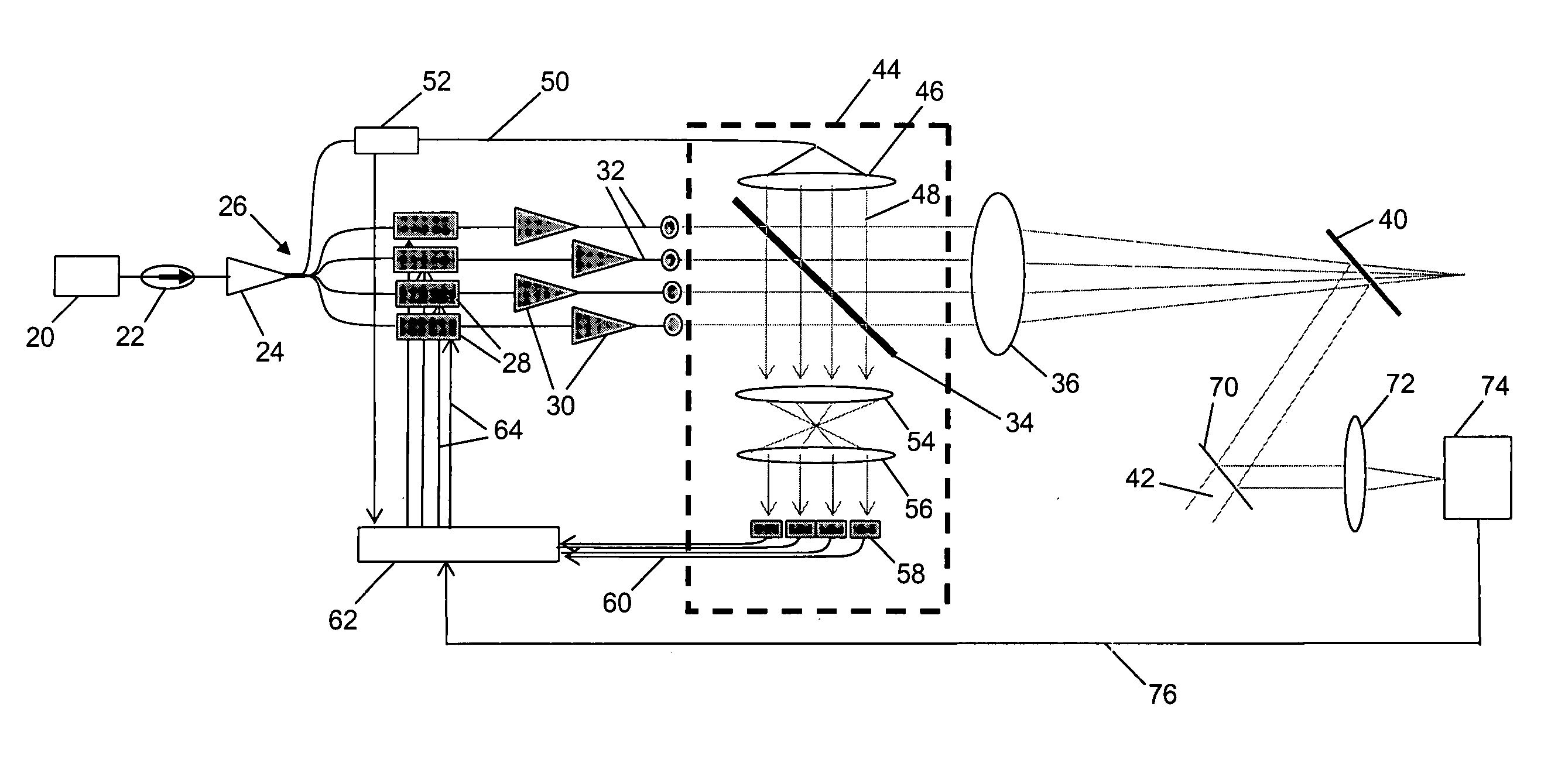
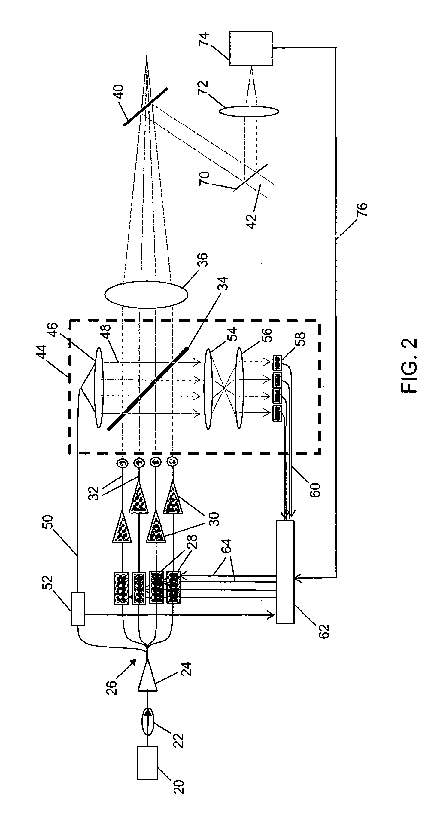
[0014] As shown in the drawings for purposes of illustration, the present invention is concerned with high power laser systems in which beams emitted from multiple fiber amplifiers are combined by means of a diffractive optical element (DOE). Since the use of a DOE is central to the invention, a brief summary of diffractive grating principles would be useful at this point.

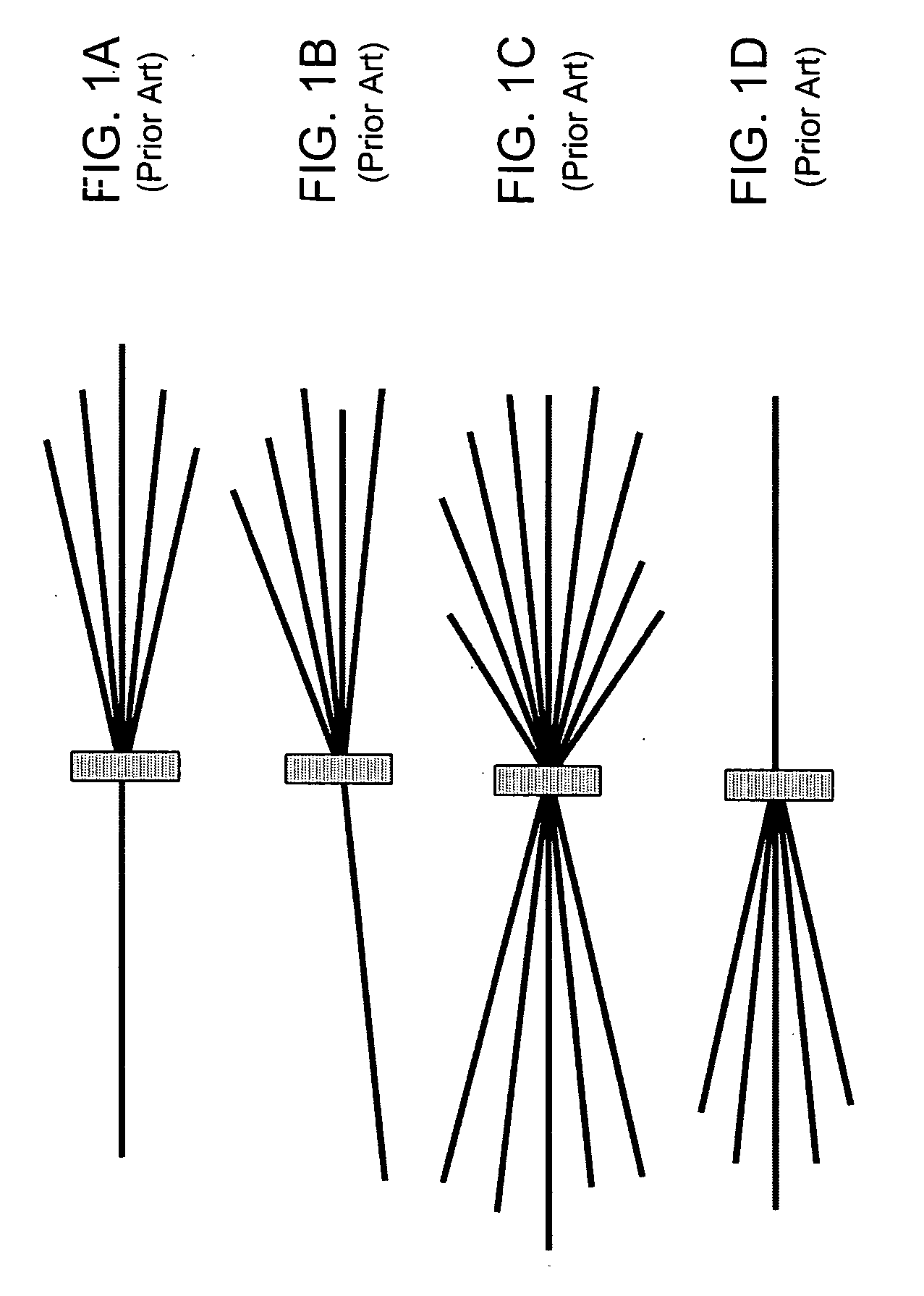
[0015] It is well known that light impinging on a plate having multiple parallel slits is diffracted in such a manner that light emerging from the multiple slits forms a characteristic interference pattern, with one central bright band and multiple, equally spaced bright bands on each side of the central band. The central band is referred to as the 0th diffraction order output, the next adjacent bands are referred to as being of diffraction orders +1 and −1, the next bands are said to of diffraction orders +2 and −2, and so forth. A transmissive diffractive grating is basically an opaque plate having a large numbe...


PUM


Abstract

An optical beam combiner and a related method for its operation, in which multiple coherent input beams are directed onto a diffractive optical element (DOE) along directions corresponding to diffraction orders of the DOE, such that the DOE generates a single output beam in a direction corresponding to a desired diffraction order, and suppresses outputs in directions corresponding to unwanted diffraction orders. The phases of the input beams are actively controlled to ensure and maintain the condition that only a single diffraction mode is present in the output of the DOE.

Description

BACKGROUND OF THE INVENTION [0001] This invention relates generally to high power lasers and, more particularly, to arrays of fiber amplifiers configured to produce a powerful composite beam. To obtain a desirably high total beam power, radiation emitting fibers are conventionally arranged in a two-dimensional array, sometimes referred to as a side-by-side array (SBSA), in which the phases of the emitters are controlled to render them mutually coherent. The beams combine in the far field as they diverge and diffract, forming the composite beam. The performance of such arrays is, however, significantly limited by the necessarily low “fill factor” of the array. Even if the fibers, which are cylindrical in shape, are closely packed in a hexagonal pattern, the fill factor is reduced by the spaces between adjacent fibers. One measure of the optical performance of such an array is the Strehl ratio of the composite beam, defined as the ratio of the on-axis intensity of the beam to the on-a...

Claims


Application Information

Patent Timeline
IPC IPC(8): G02B6/26G02B6/42
CPCH01S3/005H01S3/06754H01S3/2383H01S3/1307H01S3/10007
Inventor RICE, ROBERT REXWICKHAM, MICHAEL GORDONROTHENBERG, JOSHUA ELLIOTT
Owner NORTHROP GRUMMAN SYST CORP
Why Eureka
Try Eureka