Reducing agent container having novel structure

a reducing agent and container technology, applied in the direction of instruments, specific gravity measurement, explosions, etc., can solve the problems of difficult entry of bubbles, difficult direct passage of liquid reducing agents through space, etc., to suppress the degradation of concentration detection accuracy, improve the detection accuracy of concentration meters, and efficient defrosting

Inactive Publication Date: 2007-08-30
NISSAN DIESEL MOTOR CO
View PDF1 Cites 28 Cited by
  • Summary
  • Abstract
  • Description
  • Claims
  • Application Information

AI Technical Summary

Benefits of technology

[0010] According to the reducing agent container having a novel structure, in accordance with the present invention, the heat discharged from the lower portion of the heat exchanger is trapped in the encasing member so as to generate the convection within a region of the encasing member. The concentration meter positioned in the encasing member and the liquid reducing agent around the concentration meter are efficiently defrosted, so that a concentration detection of the liquid reducing agent can be started in a short time after an engine operation is started. Further, when the liquid reducing agent is replenished, the liquid reducing agent is swashed by the visor attached on the supporting column of the concentration meter toward the circumference of the visor. Accordingly, it becomes rather hard for the liquid reducing agent to directly pass through a space between the supporting column and the encasing member to enter the inside of the encasing member upon the replenishment. Consequently, it also becomes hard for bubbles which may be entered the inside of the encasing member together with the liquid reducing agent, to adhere to the detecting section of the concentration meter. Therefore, it is possible to suppress the degradation of the concentration detection accuracy depending on a change in the heat transmission characteristic between the two spaced points. As a result, it is possible to improve the detection accuracy of the concentration meter which detects the concentration of the liquid reducing agent, while promoting the defrosting of the liquid reducing agent stored in the reducing agent container.

Problems solved by technology

Accordingly, it becomes rather hard for the liquid reducing agent to directly pass through a space between the supporting column and the encasing member to enter the inside of the encasing member upon the replenishment.
Consequently, it also becomes hard for bubbles which may be entered the inside of the encasing member together with the liquid reducing agent, to adhere to the detecting section of the concentration meter.

Method used


Image

  • Reducing agent container having novel structure
  • Reducing agent container having novel structure
  • Reducing agent container having novel structure

Examples


Embodiment Construction

[0020] Hereunder, there will be described several embodiments of the present invention with reference to the accompanying drawings.

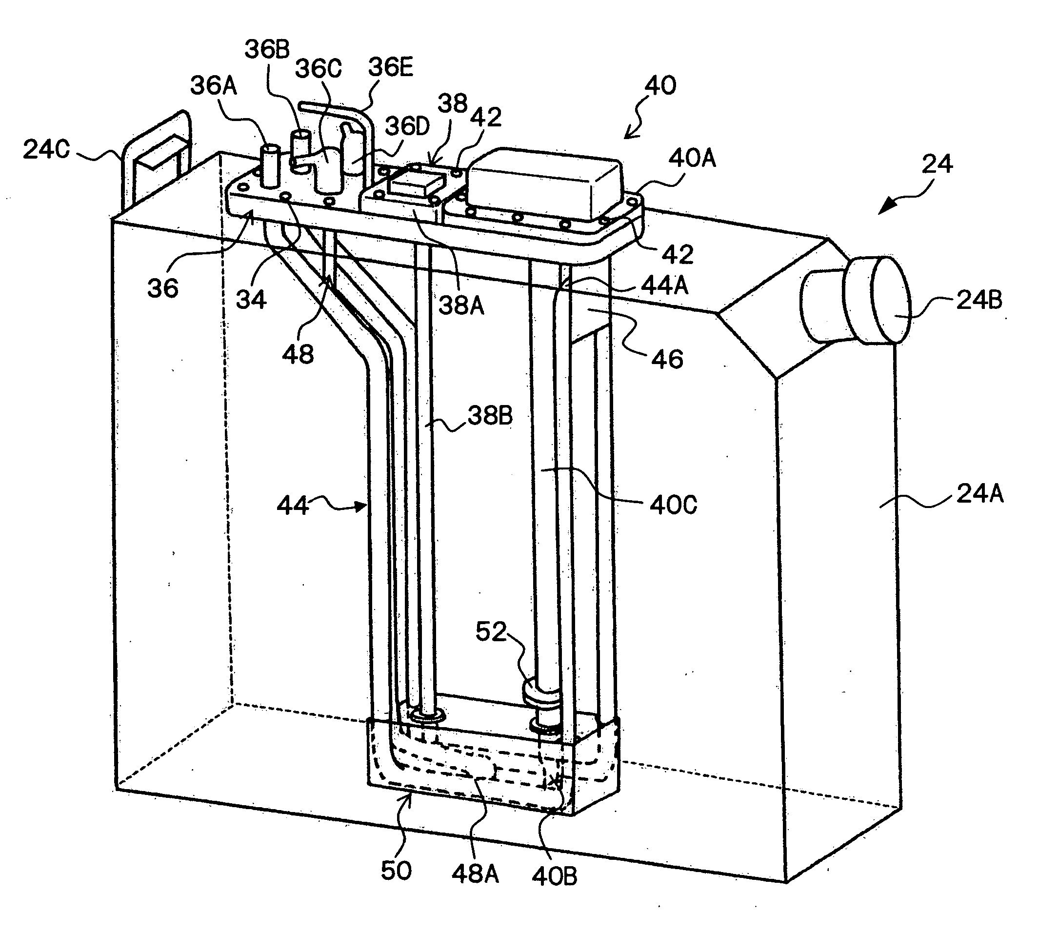
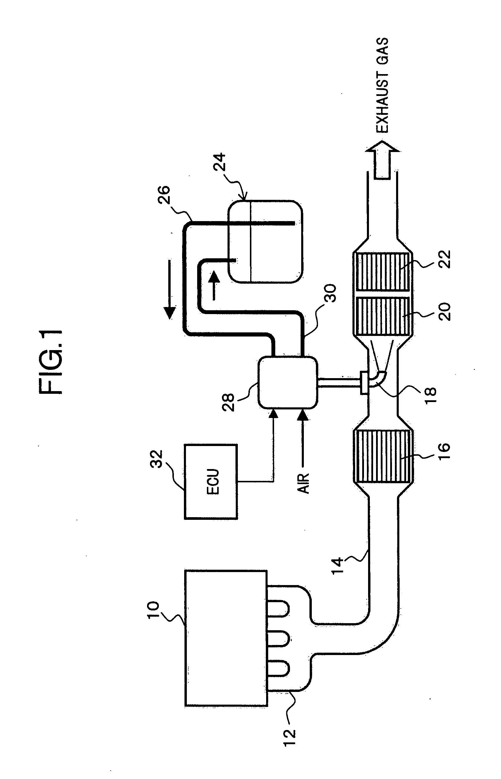
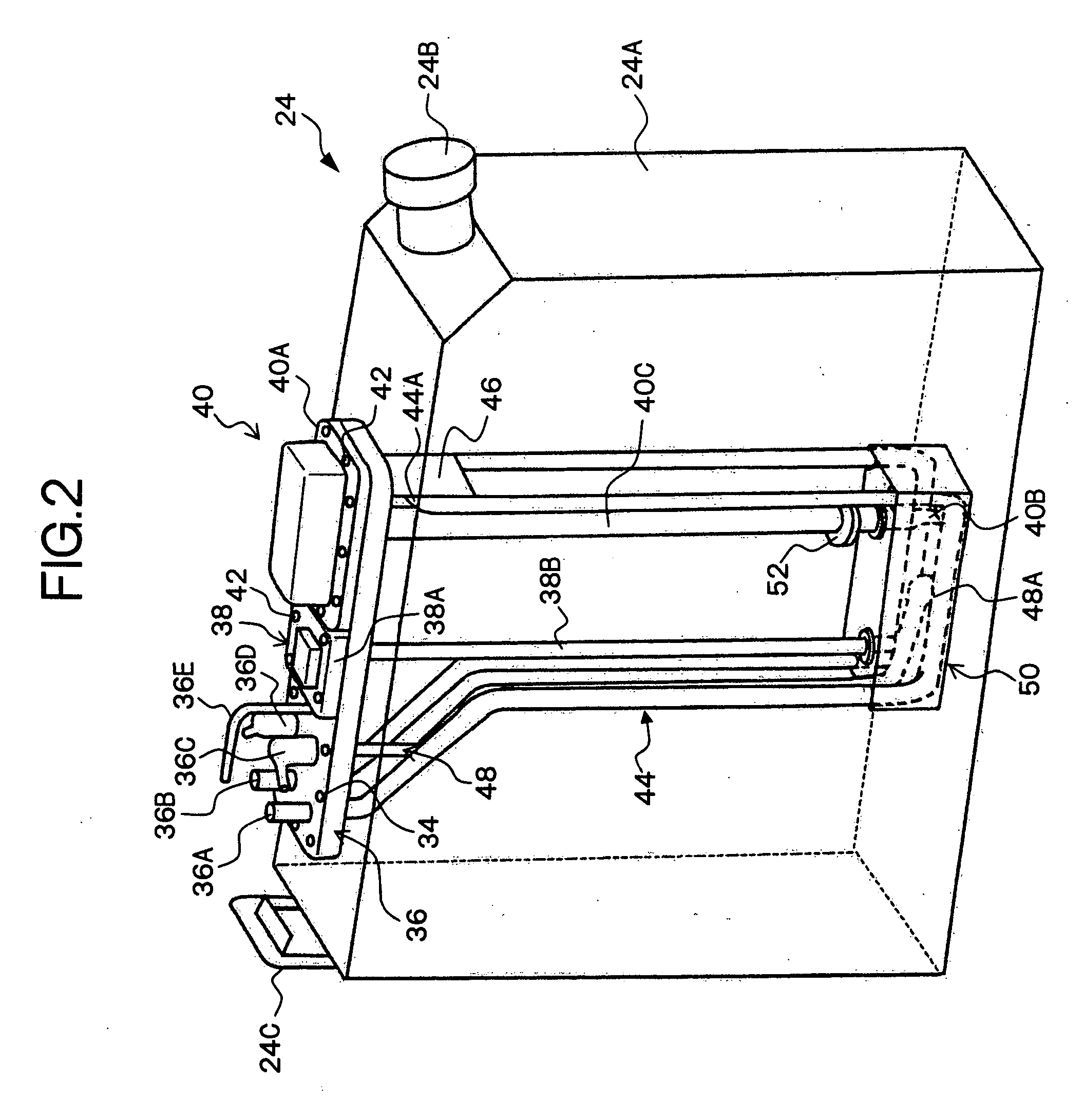
[0021]FIG. 1 shows an overall configuration of an exhaust emission purifying apparatus for purifying NOx contained in the exhaust gas of an engine by the catalytic-reduction reaction, using the urea aqueous solution as a liquid reducing agent, and to this type of exhaust emission purifying apparatus, the present invention may be typically applied, as will be understood from the ensuing description.

[0022] In an exhaust pipe 14 connected to an exhaust manifold 12 of an engine 10, there are disposed respectively, along an exhaust gas flow direction, an oxidation catalytic converter 16 for oxidizing nitrogen monoxide (NO) into nitrogen dioxide (NO2), an injection nozzle 18 for injection-supplying the urea aqueous solution, a NOx reduction catalytic converter 20 for reductively purifying NOx with ammonia obtained by hydrolyzing the urea aqueous solution, an...


PUM

PropertyMeasurementUnit
structureaaaaaaaaaa
concentration meteraaaaaaaaaa
concentrationaaaaaaaaaa

Abstract

On an upper surface of a container body, there are disposed at least a base portion of a concentration meter configured to detect the concentration of a liquid reducing agent based on a heat transmission characteristic between two spaced points, and a heat exchanger configured to permit the engine coolant to circulate therein and arranged to surround a detecting section of the concentration meter, which hangs from the base portion of the concentration meter via a supporting column thereof, to thereby perform the heat exchange with the liquid reducing agent, and also, a protector or an encasing element of substantially box shape is arranged to surround a lower portion of the heat exchanger and the detecting section of the concentration meter, and further, a visor is attached on the supporting column of the concentration meter, which is positioned above the protector by a predetermined interval.

Description

[0001] This application is a continuation of PCT / JP2005 / 017129, filed on Sep. 16, 2005.BACKGROUND OF THE INVENTION [0002] 1. Field of the Invention [0003] The present invention relates generally to an exhaust emission purifying apparatus for reductively purifying nitrogen oxides (NOx), and in particular, to a technology for increasing a detection accuracy of a concentration meter which is configured to detect the concentration of a liquid reducing agent based on a heat transmission characteristic between two spaced points while accelerating the defrosting of the liquid reducing agent stored in a reducing agent container in the exhaust emission purifying apparatus for reductively purifying NOx. [0004] 2. Description of the Related Art [0005] Japanese Unexamined Patent Publication No. 2000-27627 discloses an exhaust emission purifying apparatus as one proposal for a catalytic converter purifying system for eliminating NOx contained in the exhaust gas from an engine. In such an exhaust...

Claims


Application Information

Patent Timeline
Patent Type & Authority Applications(United States)
IPC IPC(8): C06B21/00F01N3/08F01N3/20F01N3/24
CPCF01N3/2066F01N2610/02F01N2610/10F01N2610/1406Y02T10/24F01N2610/1486F01N2900/1814F01N2900/1818F01N2610/148Y02T10/12
Inventor NISHINA, MITSUHIROMATSUNAGA, HIDEKIINOUE, SHINICHINAKAMURA, TOSHIMI
Owner NISSAN DIESEL MOTOR CO
Why Eureka
Try Eureka