
Fuel Cell System And Fuel Cell System Failure Judgment Method

a fuel cell system and fuel cell technology, applied in the direction of fuel cells, electrochemical generators, electrical equipment, etc., can solve the problems of increasing the electric power consumption of auxiliary devices, rapid failure detection in a reaction, and a lot of time, so as to reduce the electric power conversion efficiency, increase the consumption of electric power, and accelerate the consumption of reaction gas

Active Publication Date: 2007-08-30
TOYOTA JIDOSHA KK
View PDF6 Cites 45 Cited by
  • Summary
  • Abstract
  • Description
  • Claims
  • Application Information

AI Technical Summary

Benefits of technology

The present invention provides a fuel cell system that can quickly detect and diagnose failures in the reaction gas passage, which is important for the fuel cell's performance and safety. The system achieves this by increasing the consumption of reaction gas in the failure detection portion of the reaction gas passage by increasing the electric power consumption of auxiliary devices. This allows for a rapid failure judgment and ensures that the system can operate efficiently and safely.

Problems solved by technology

In the case of insufficient fuel consumption of the fuel cell and the combustion chamber, however, a lot of time is required until the pressure of the fuel gas supply system decreases, which inhibits rapid failure detection in a reaction gas passage.
With this arrangement, where the electric power generation of the fuel cell and the electric power consumption of the auxiliary devices result in an insufficient consumption of the reaction gas, the reaction gas consumption can be accelerated by increasing the electric power consumption of the auxiliary devices.

Method used


Image

  • Fuel Cell System And Fuel Cell System Failure Judgment Method
  • Fuel Cell System And Fuel Cell System Failure Judgment Method
  • Fuel Cell System And Fuel Cell System Failure Judgment Method

Examples


Embodiment Construction

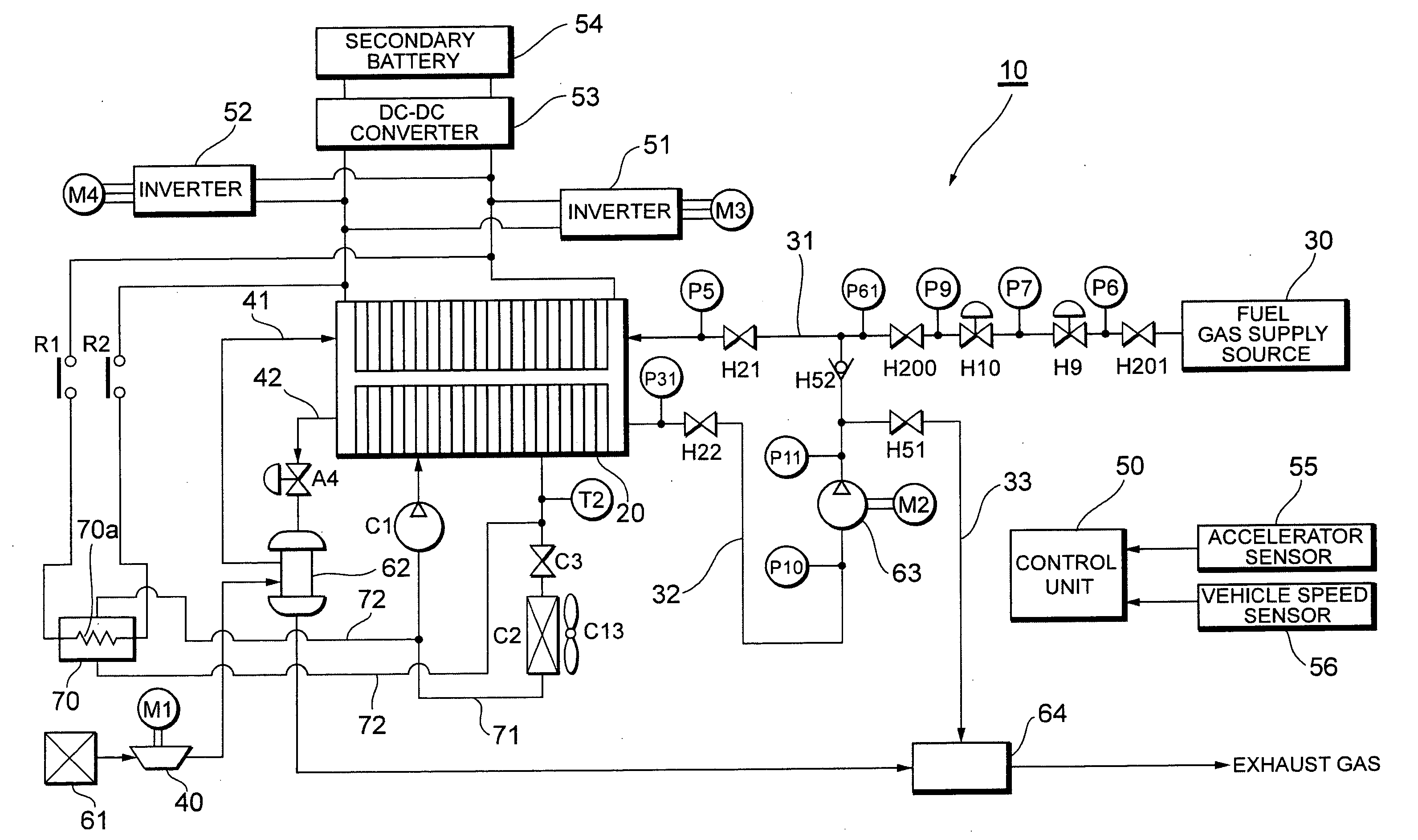
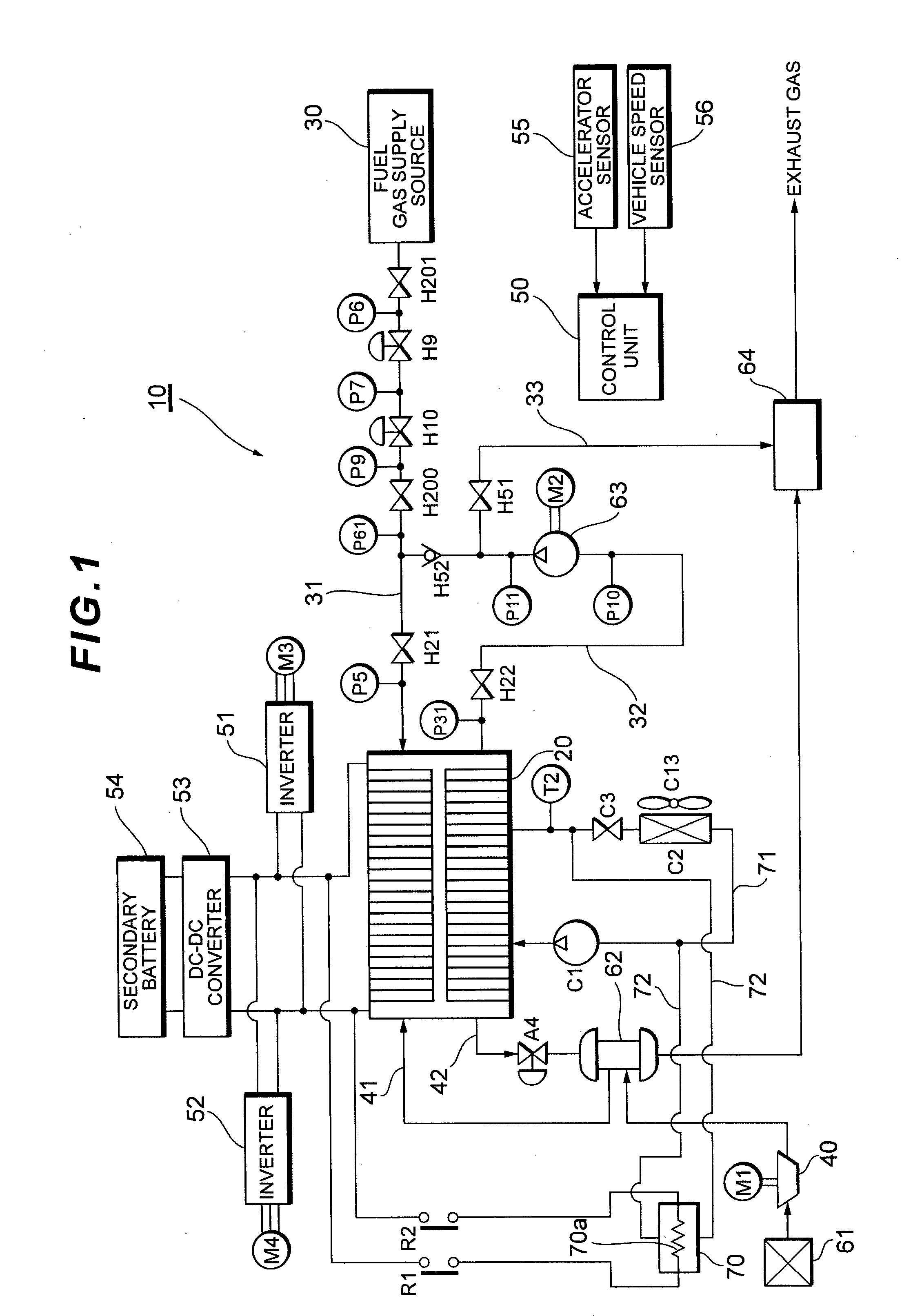
[0039] Referring to FIG. 1, there is shown an outline configuration of a fuel cell system according to this embodiment. While this specification describes an example in which a fuel cell system 10 is used as an on-board power generating system for a fuel cell hybrid vehicle (FCHV), it can also be used as a stationary power generating system. A fuel cell (fuel cell stack) 20 has a stack structure in which a plurality of single cells are stacked in series: for example, it includes solid polymer electrolyte fuel cells.

[0040] A fuel gas supply system (fuel gas pipeline) of the fuel cell 20 includes a fuel gas supply source 30, a fuel gas supply passage 31, and a fuel gas circulating passage 32 arranged therein. It should be noted here that the fuel gas supply system is a generic name given to gas piping and valves arranged in a passage for supplying fuel gas from the fuel gas supply source 30 to the fuel cell 20, for example, including the fuel gas supply source 30, the fuel gas supply...


PUM

PropertyMeasurementUnit
electric power consumptionaaaaaaaaaa
temperatureaaaaaaaaaa
heat lossaaaaaaaaaa

Abstract

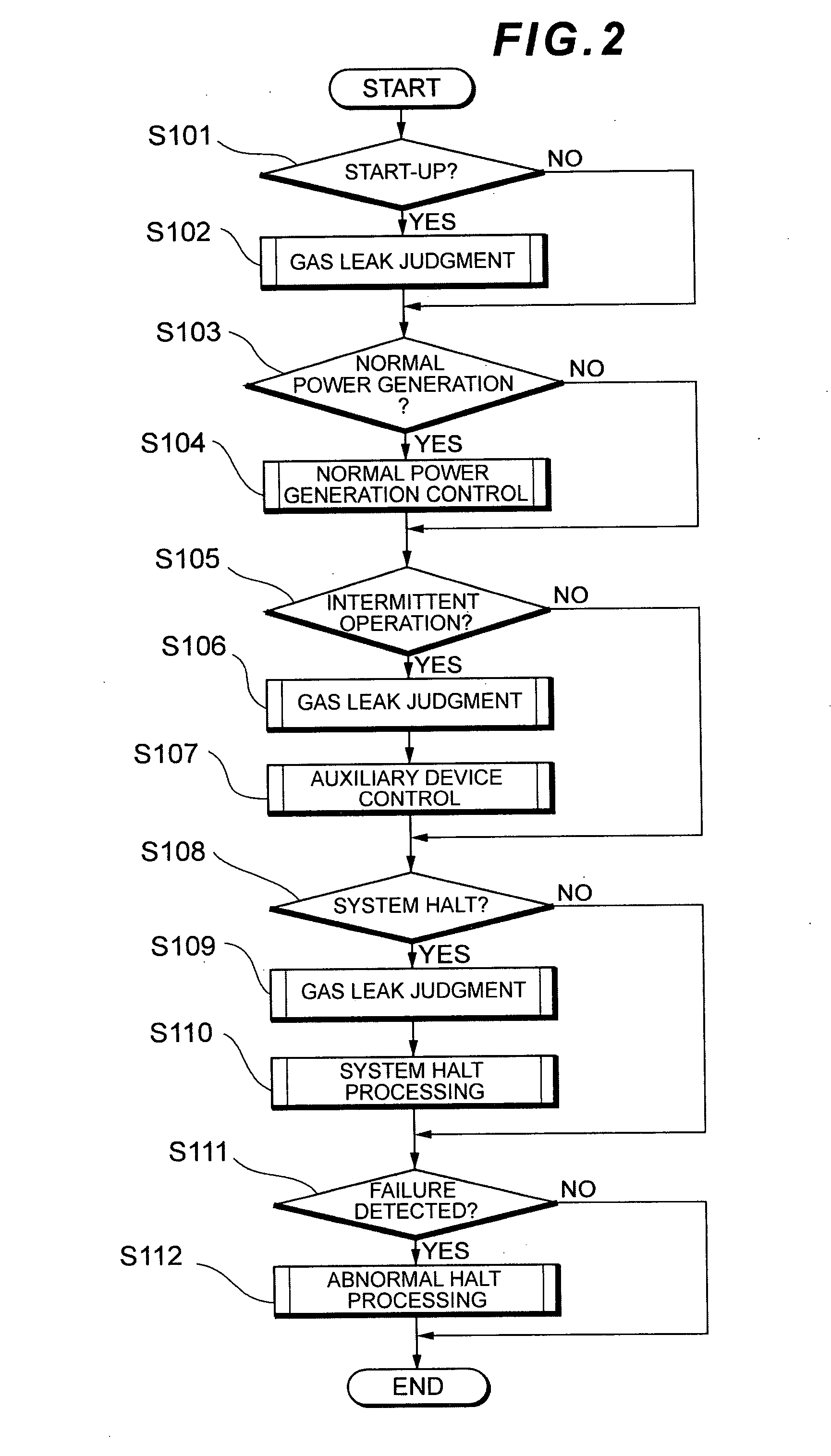
A fuel cell system is provided with a judgment unit which makes a gas leak judgment based on a pressure drop of fuel gas in a gas leak detection portion by consuming the fuel gas in the gas leak detection portion of the fuel gas supply system by electric power generation of a fuel cell and causing auxiliary devices to consume the electric power generated by the fuel cell, and comprises a control unit which increases consumption of the fuel gas in the gas leak detection portion by increasing the electric power consumption of the auxiliary devices. With this arrangement, where the electric power generation of the fuel cell and the electric power consumption of the auxiliary devices result in an insufficient consumption of the fuel gas, the consumption of the fuel gas can be accelerated by increasing the electric power consumption of the auxiliary devices. Thereby, a rapid gas leak judgment can be achieved.

Description

BACKGROUND [0001] The present invention relates to a fuel cell system and a fuel cell system failure judgment method, and more particularly to an improved technology for use in performing failure detection and judgment in a reaction gas passage accurately in a short time. [0002] As a power generating system for a fuel cell hybrid vehicle, there has been used a fuel cell system capable of directly deriving chemical energy, which has been generated by a redox reaction of reaction gas (fuel gas or oxide gas), as electric energy. In this type of fuel cell system, various shut-off valves (for example, a high-pressure hydrogen tank valve, a hydrogen supply valve, an FC inlet valve, an FC outlet valve, a purge valve, and the like) are arranged in a fuel gas supply passage for use in supplying fuel gas from a hydrogen supply source to a fuel cell. [0003] As a failure diagnosis technique for these various shut-off valves, for example, Japanese Patent Laid-Open No. 2000-274311 has suggested a...

Claims


Application Information

Patent Timeline
Patent Type & Authority Applications(United States)
IPC IPC(8): H01M8/04
CPCH01M8/04089H01M8/04097H01M8/04358H01M8/04365H01M8/04388Y02E60/50H01M8/04664H01M8/04679H01M8/04723H01M8/04731H01M8/04947H01M8/04402
Inventor YOSHIDA, NAOHIRO
Owner TOYOTA JIDOSHA KK
Learn More