Control system for power transmission unit of vehicle

a technology of power transmission unit and control system, which is applied in the direction of machines/engines, batteries/cells, and gearing, etc., can solve the problems of periodic fluctuation of torque input from the driving wheel side, and achieve the effect of reducing torque capacity, effective dampening of resonance, and improving durability of the vehicl

Active Publication Date: 2007-08-30
TOYOTA JIDOSHA KK
View PDF5 Cites 63 Cited by
  • Summary
  • Abstract
  • Description
  • Claims
  • Application Information

AI Technical Summary

Benefits of technology

[0016]Therefore, a plurality of resonance dampening controls are carried out according to priority. For this reason, the resonance can be dampened effectively. Moreover, an appropriate resonance dampening control can be carried out according to a condition of the vehicle, therefore, the durability of the vehicle can be improved.
[0017]Preferably, in addition to the above, the power transmission unit comprises a clutch mechanism capable of changing a transmission torque capacity thereof, and the resonance dampening control device includes a device for carrying out a control of reducing the torque capacity of the clutch mechanism as a priority resonance dampening control, thereby the resonance is dampened by controlling the clutch mechanism such as a clutch and a brake on a priority basis. For this reason, the resonance is dampened easily and effectively.
[0018]Preferably, in addition to the above, the prime mover includes an internal combustion engine capable of changing an operating point thereof governed by an output torque and a revolution frequency or momentums corresponding to those factors; the power transmission unit includes at least any of a clutch mechanism, a transmission capable of varying a speed change ratio, and a differentia

Problems solved by technology

Moreover, no small clearance should exist in some part of the power transmission line and this causes a chattering.
Further, a r

Method used


Image

  • Control system for power transmission unit of vehicle
  • Control system for power transmission unit of vehicle
  • Control system for power transmission unit of vehicle

Examples


Embodiment Construction

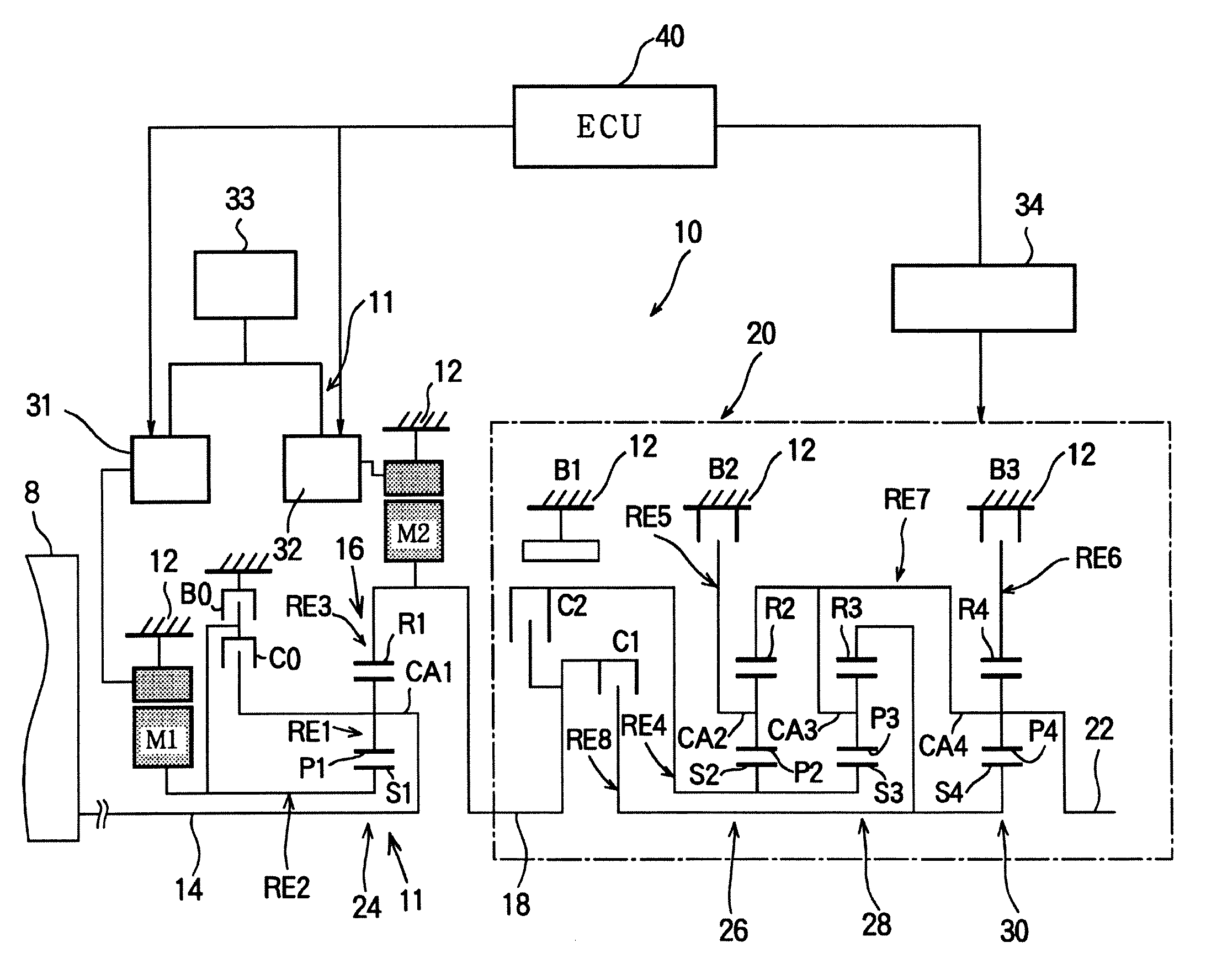
[0033]Next, this invention will be described in connection with its specific examples. A power transmission unit to which the invention is applied will be explained first of all. FIG. 3 is a skeleton diagram illustrating a power transmission unit 10 for hybrid vehicles to which a control system as one example of the invention is applied. As illustrated in FIG. 3, the power transmission unit 10 comprises, an input shaft 14 as an input rotary member arranged coaxially in a non-rotatable transmission case 12 (as will be called as a case 12 hereinafter) of a vehicle, an electrical continuously variable transmission part 11 connected to the input shaft 14 directly or indirectly through a not shown pulsation absorbing damper (i.e., a vibration dampening device), a mechanical transmission part 20 functioning as a geared transmission connected in tandem through a transmission member (i.e., a transmission shaft) 18 on a power transmission route between the continuously variable transmission ...


PUM


Abstract

A control system for a power transmission unit of a vehicle transmitting power outputted from a prime mover, comprising: a resonance detecting/predicting device for detecting or predicting a generation of a resonance of the power transmission unit resulting from a power transmission; a driving condition detecting device for detecting a driving condition of a vehicle in case the generation of a resonance is detected or predicted by the resonance detecting/predicting device; and a resonance dampening control selecting device for changing contents of a control for dampening the detected or predicted resonance on the basis of the driving condition of the vehicle detected by the driving condition detecting device.

Description

BACKGROUND OF THE INVENTION[0001]1. Field of the Invention[0002]This invention relates generally to a system for controlling a power transmitting condition of a power transmission unit mounted on a vehicle, and more particularly, to a control system for dampening a resonance resulting from a transmission of power.[0003]The disclosure of Japanese Patent Application No. 2006-053622 filed on Feb. 28, 2006 including specification, drawings and claims is incorporated herein by reference in its entirety.[0004]2. Related Art[0005]An internal combustion engine such as a gasoline engine is conventionally used as a prime mover of a vehicle, and a power transmission system for transmitting a power to a driving wheel is composed mainly of a speed change mechanism. As a speed change mechanism, a geared transmission varying a speed change ratio stepwise, and a continuously variable transmission varying a speed change ratio continuously are widely known. Additionally, in recent years, an apparatus...

Claims


Application Information

Patent Timeline
IPC IPC(8): B60K1/02B60K6/00B60K6/445B60K6/547B60W10/00B60W10/02B60W10/04B60W10/06B60W10/10B60W10/11B60W10/115B60W20/00F02D29/00F16D48/02F16H59/68F16H61/02F16H61/68F16H61/684F16H61/686
CPCB60K1/02Y10T477/641B60K6/40B60K6/445B60K6/547B60L11/123B60L11/14B60L2270/145B60W10/02B60W10/06B60W10/08B60W10/11B60W10/12B60W20/00B60W30/20F16H3/728F16H2037/0873F16H2200/201F16H2200/2012F16H2200/2038F16H2200/2041F16H2200/2046F16H2200/2048Y02T10/6217Y02T10/6286Y02T10/7005Y02T10/7077Y02T10/84Y02T10/6239Y10T477/23B60K6/365B60L50/61B60L50/16Y02T10/62Y02T10/7072Y02T10/70B60W10/115B60W20/30
Inventor KAKINAMI, TAKUMAIWASE, YUJITABATA, ATSUSHIMATSUBARA, TOORUSHIBATA, HIROYUKI
Owner TOYOTA JIDOSHA KK
Why Eureka
Try Eureka