Actuator control system and method

a control system and actuator technology, applied in the direction of clutches, servomotor circuits, fluid couplings, etc., can solve the problems of complex and expensive high-pressure hydraulic piping networks, large power losses through the piping network, and major expense, so as to eliminate centralized high-pressure hydraulic systems and costly high-pressure plant-wide hydraulic plumbing

Inactive Publication Date: 2007-09-06
JACOBS MICHAEL H +2
View PDF10 Cites 15 Cited by
  • Summary
  • Abstract
  • Description
  • Claims
  • Application Information

AI Technical Summary

Benefits of technology

[0010] In general, and in one aspect, an embodiment of the invention provides an EVS actuator control system which is contained in a standard NEMA electrical enclosure for providing a compact point-of-use EVS actuator control system which can be located on or close to the equipment being operated thereby eliminating centralized high-pressure hydraulic systems and costly high-pressure plant wide hydraulic plumbing.

Problems solved by technology

Current systems and methods for generating velocity and force using hydraulics as the transmission medium have numerous problems.
For example, commonly used centralized high pressure hydraulic systems are designed for plant wide use which requires complex and expensive high pressure hydraulic piping networks to the point of use.
Thus, the installation of this piping network is both time consuming and laborious thereby resulting in a major expense and an operational problem that causes schedule delays.
Costly power losses through the piping network are also significant.
There is also a problem with leaking pipe joints and connections that waste power and create operational hazards.
Hence, the piping network often costs more than the operational components.
Current centralized high pressure hydraulic systems also require large oil reservoirs with hydraulic filtration and oil cooling components, expensive high-pressure hydraulic pumps that sense the load requirements and adjust the velocity of linear or rotary actuators, expensive high-pressure hydraulic valves used to limit horsepower and control the force and velocity of hydraulic actuators, high-pressure hydraulic directional valves to control the direction of movement of the linear or rotary hydraulic actuators, and expensive remote sensing devices that signal the velocity of the linear or rotary hydraulic actuators.
Hence, current centralized high pressure hydraulic systems require considerable physical space for both the placement of the central system and the associated piping.
Furthermore, current centralized high pressure hydraulic systems and methods utilize electric motors as a “prime mover” which are repeatedly started and stopped thereby creating a large electric current draw which increases the system acquisition cost as well as operational cost.
Alternatively, the electric motors run constantly, most often in a “stand-by” mode wasting electric power and causing wear on system components.
Thus, the velocity and force control with current methods involves complex systems that generate heat and waste horsepower.
Moreover, current centralized high pressure hydraulic systems and methods, in many applications, require feedback signals to travel long distances often resulting in system failure.

Method used


Image

  • Actuator control system and method
  • Actuator control system and method
  • Actuator control system and method

Examples


Embodiment Construction

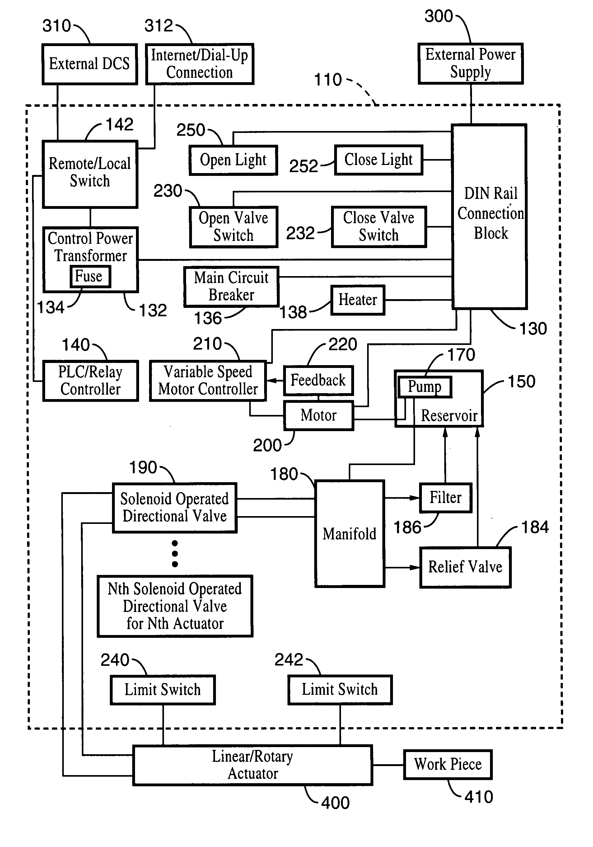
[0026] Considering the drawings, wherein like reference numerals denote like parts throughout the various drawing figures, reference numeral 110 is directed to an electronic variable speed (EVS) actuator control system.

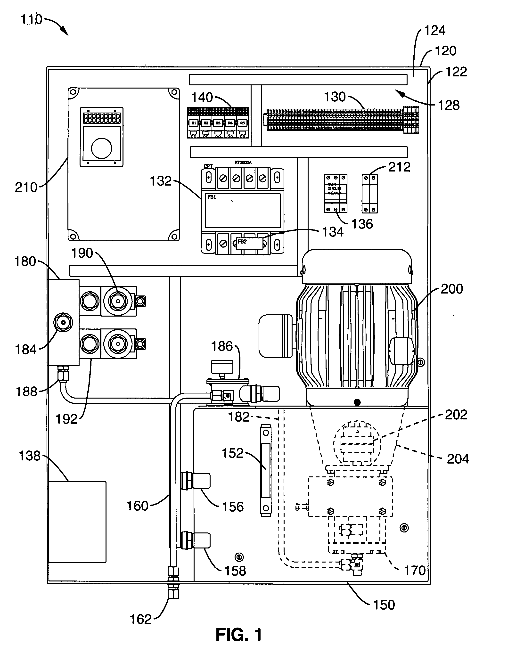
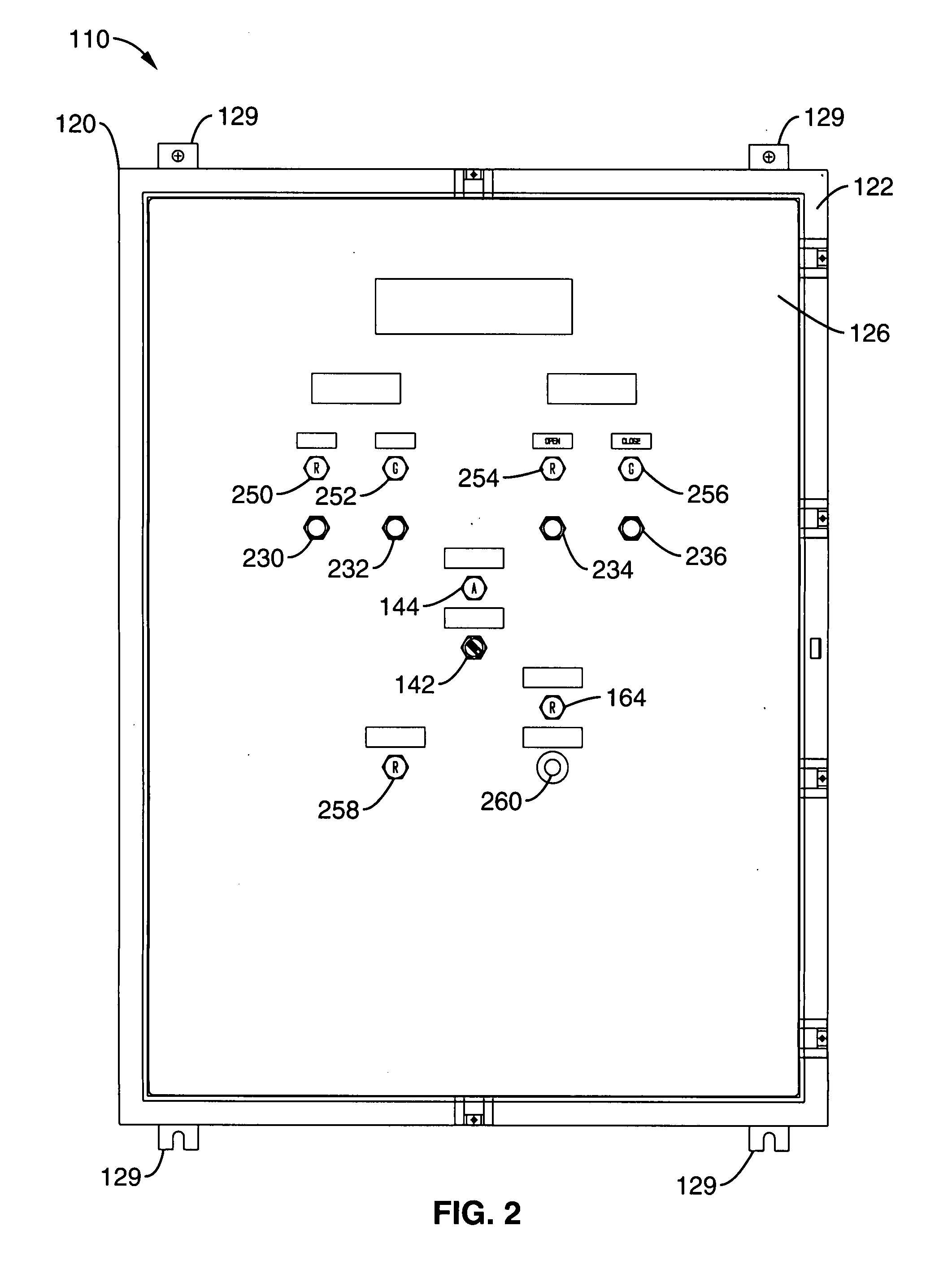
[0027] In general, and referring to FIGS. 1 through 4, an embodiment of the invention provides an electronic variable speed (EVS) actuator control system 110 enclosed in a NEMA electrical enclosure 120 and powered from an external power supply 300 for providing electronic velocity and force control of actuation of at least one external high-pressure hydraulic linear and / or rotary actuator 400 working on work piece 410. The electrical enclosure 120 is comprised of a four sided construct 122 extending substantially perpendicularly between a back cover 124 and a front cover 126 wherein an internal cavity 128 is defined by the four sided construct 122 and back cover 124 and is accessible through front cover 126 shown in FIG. 2. The NEMA electrical enclosure 120 can be mo...


PUM


Abstract

Actuator control system and method comprising an electric motor driving a hydraulic pump in fluid delivery communication with a source of hydraulic fluid; a variable speed controller operatively coupled to the motor for driving the pump at variable speeds; an external hydraulic actuator in fluid delivery communication with the pump for receiving pressurized fluid flow from the pump; and a feedback loop operatively coupled from the motor to the controller for providing feedback signals correlative to a pressure of the pressurized fluid flow through the driven pump for driving the external hydraulic actuator in response to the feedback signals for providing electronic velocity and force control of actuation of the external hydraulic actuator. The actuator control system and method can operate on one or many high-pressure hydraulic linear and/or rotary actuators on different pieces of hydraulically driven equipment and with different velocity requirements actuating in different directions.

Description

CROSS-REFERENCE TO RELATED APPLICATION [0001] This application claims priority to U.S. Provisional Patent Application No. 60 / 760,572, filed Jan. 20, 2006, the entire disclosure of which is incorporated herein by reference. FIELD OF THE INVENTION [0002] This invention relates generally to an actuator control system and method and, in particular, to an electronic variable speed (EVS) actuator control system and method for electronic velocity and force control of actuation of high-pressure hydraulic linear and / or rotary actuators. BACKGROUND OF THE INVENTION [0003] Current systems and methods for generating velocity and force using hydraulics as the transmission medium have numerous problems. [0004] For example, commonly used centralized high pressure hydraulic systems are designed for plant wide use which requires complex and expensive high pressure hydraulic piping networks to the point of use. Thus, the installation of this piping network is both time consuming and laborious thereby...

Claims


Application Information

Patent Timeline
Patent Type & Authority Applications(United States)
IPC IPC(8): F16D31/02
CPCF15B21/087F15B2211/20515F15B2211/20538F15B2211/7058F15B2211/6655F15B2211/6656F15B2211/7053F15B2211/633
Inventor JACOBS, MICHAEL H.COWAN, KENNETH SEANRASMUSSEN, ALLEN L.
Owner JACOBS MICHAEL H
Why Eureka
Try Eureka