Connector pins cutting machine

Inactive Publication Date: 2007-09-06
CHENG UEI PRECISION IND CO LTD
View PDF8 Cites 2 Cited by
  • Summary
  • Abstract
  • Description
  • Claims
  • Application Information

AI Technical Summary

Benefits of technology

[0006] Accordingly, an object of present invention is to provide a connector pins cutting machine which can provide a high qualified rate in production of the connectors.
[0009] Constructed as mentioned-above, the connector pins cutting machine can provides predetermined and constant cutting force and cutting dimensions to the pins, thereby decreasing the unqualified rate of the connectors. Furthermore, the connector pins cutting machine is driven by special driving member, so less manual labor is needed, thereby the connector pins cutting machine is adapted to be applied in mass production of connectors.

Problems solved by technology

However, some of these connector pins are functional pins which need to be soldered with the wires of the cable so as to transmit electric power or signals, others of these connector pins are idle pins which have no actual use and need not to be soldered with the wires of the cable.
However, in prior art, the soldering portions of these idle pins are often cut by pliers by manual manipulation, the cutting force acted on the pins and the cutting dimensions of the pins are more difficult to control, thereby there may be a high unqualified rate of the products in this producing manner.
Furthermore, more manual labor is needed in producing, which increase the producing cost so that cannot be applied in mass production of the connectors.

Method used


Image

  • Connector pins cutting machine
  • Connector pins cutting machine
  • Connector pins cutting machine

Examples


Embodiment Construction

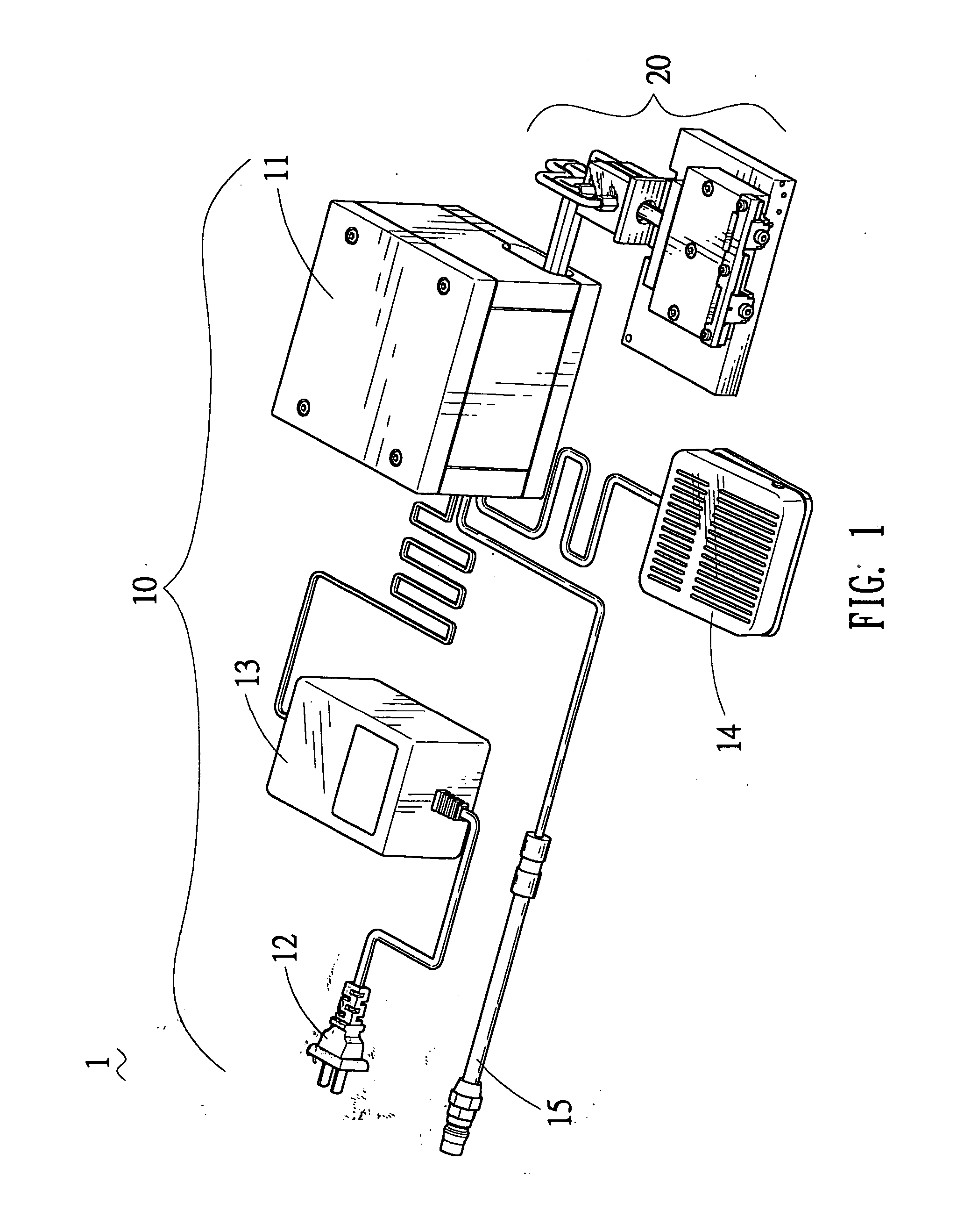
[0021] With reference to FIG. 1, a connector pins cutting machine 1 according to the present invention is illustrated, which includes a cutting system 20 and a power supply system 10 for supplying driving power to the cutting system 20. The power supply system 10 includes a high pressure air feeding pipe 15 for providing high pressure air, a relay device 11 connected with the air feeding pipe 15 for controlling how the high pressure air will be fed to the cutting system 20, a power plug 12 for obtaining original electric power from a power source, a transformer 13 connected between the power plug 12 and the relay device 11 for transforming the original electric power to a proper voltage electric power matching with the relay device 11, and a switch 14 connected with the relay device 11 for switching the relay device 11 on and off.

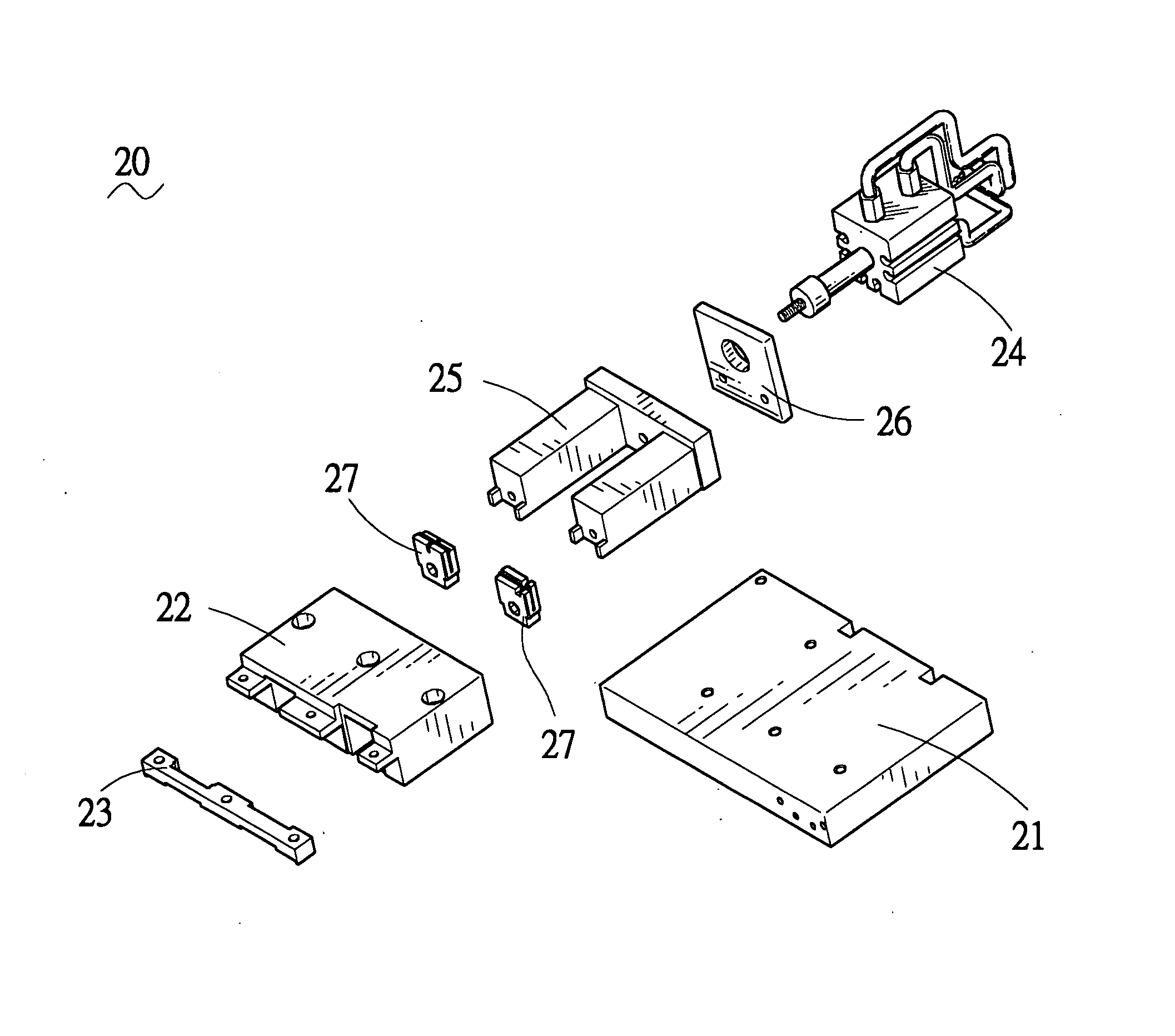
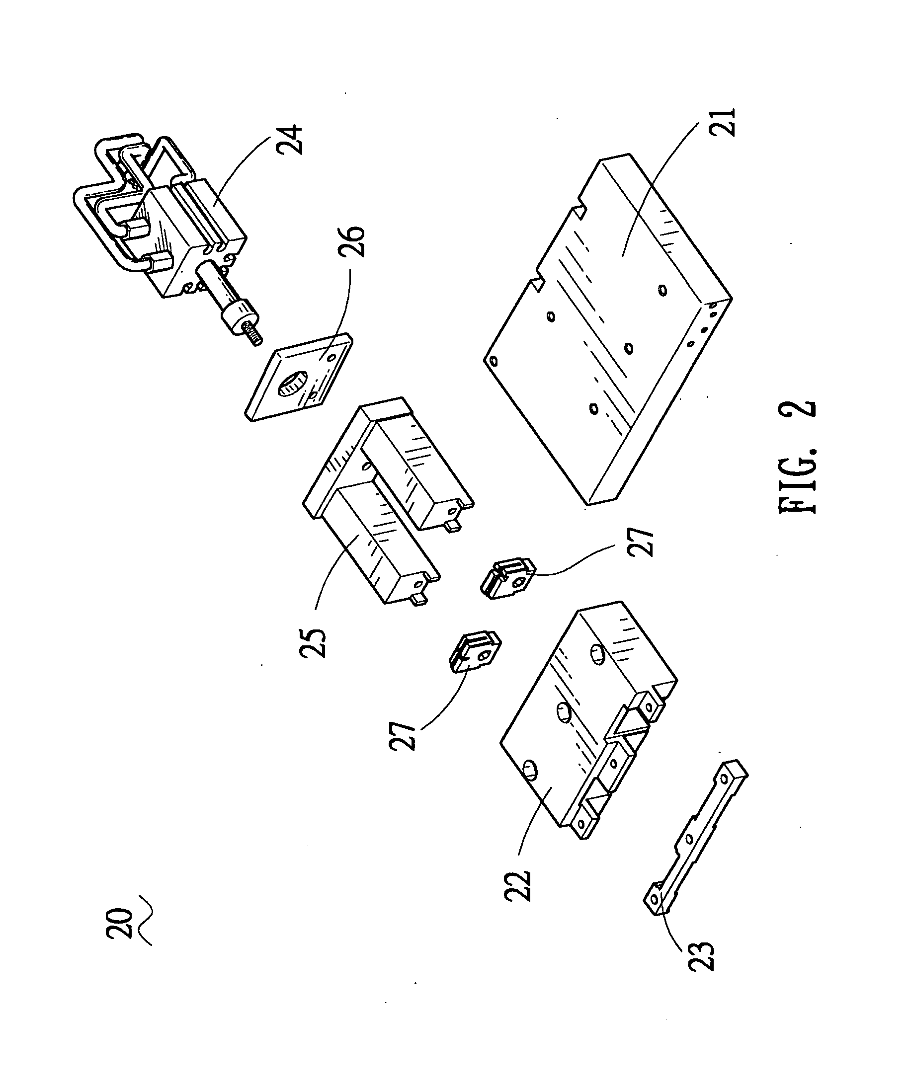
[0022] Please refer to FIG. 2 in conjunction with FIG. 8. The cutting system 20 includes a base member 21, a containing member 22 mounted on the base memb...


PUM


Abstract

A connector pins cutting machine for cutting soldering portions of idle pins of a connector includes a base member, a containing member mounted on the base member having at least one sliding groove extending there-through, a connector positioning member coupled to the containing member having at least one connector-positioning recess for positioning the connector with the soldering portions of the idle pins extending into the sliding groove, a propeller slidably contained in the sliding groove, a cutting member installed on a front end of the propeller, and a driving member fixed to a rear end of the propeller for driving the propeller together with the cutting member to reciprocate in the sliding groove. Thereby, the soldering portions in the sliding groove are cut by the cutting member.

Description

BACKGROUND OF THE INVENTION [0001] 1. Field of the Invention [0002] The present invention relates to a machine for processing electrical connectors, and more particularly, to a machine for cutting pins of the electrical connectors. [0003] 2. The Related Art [0004] We know existing connectors for cables are mostly constructed from insulating housings and multiple conductive connector pins. The connector pins are used for transmitting electric power or signals. The insulating housing holds these conductive pins therein for insulating these pins from outside and simultaneously to avoid these pins being into contact with each other. Each pin has a soldering portion for being soldered with one according electric wire of the cable. For conforming with technical standards governing dimensional configuration and electrical characteristics, the housings of the existing connectors often have been available in various designate size and shapes, and a lot of connector pins are commonly disposed...

Claims


Application Information

Patent Timeline
IPC IPC(8): B26D1/04
CPCH01R43/16Y10T83/8821
Inventor YU, GAO-HUAHUANG, SHENG
Owner CHENG UEI PRECISION IND CO LTD
Why Eureka
Try Eureka