
Hydrogen-oxygen fuel cell pole plate and manufacturing method thereof

A fuel cell plate and manufacturing method technology, which is applied to fuel cells, circuits, electrical components, etc., can solve problems such as difficulty in ensuring sealing and encapsulation effects, complex fabrication of metal flow field plates, and complex sealing process of electrode plates, etc., to achieve enhanced anti-corrosion Cross-leakage performance, shortened production cycle, light weight effect

Pending Publication Date: 2021-06-04
魔方氢能源科技(江苏)有限公司
View PDF1 Cites 0 Cited by
  • Summary
  • Abstract
  • Description
  • Claims
  • Application Information

AI Technical Summary

Problems solved by technology

This kind of electrode plate is heavy, and at the same time, the metal flow field plate is complicated to manufacture, and the later sealing process of the electrode plate is complicated, so it is difficult to ensure the sealing effect

Method used


Image

  • Hydrogen-oxygen fuel cell pole plate and manufacturing method thereof
  • Hydrogen-oxygen fuel cell pole plate and manufacturing method thereof
  • Hydrogen-oxygen fuel cell pole plate and manufacturing method thereof

Examples


Embodiment 1

[0040] Such as Figure 6 As shown, this embodiment proposes a hydrogen-oxygen fuel cell plate, including a cathode plate and an anode plate that are bonded to each other, wherein the anode plate includes a hydrogen flow field plate 1, a water flow field plate 2 and a gas barrier conductive film 4, The cathode plate includes an air-oxygen flow field plate 3, a water flow field plate 2 and a gas-barrier conductive film 4, and the hydrogen flow field plate 1, the air-oxygen flow field plate 3 and the water flow field plate 2 are plates made of a mixture of graphite and resin The hydrogen flow field plate 1, the air oxygen flow field plate 3 and the water flow field plate 2 all have a plane surface on one side, and a flow field on the other side surface, and the plane side of the hydrogen flow field plate 1 and the water flow field The plane side of the plate 2 is attached to both sides of a gas barrier conductive film 4 to form an anode plate, and the plane side of the air oxygen...

Embodiment 2

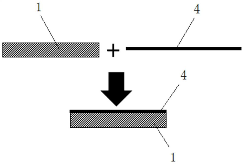
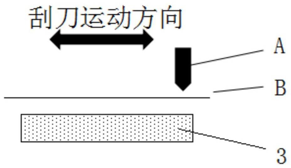
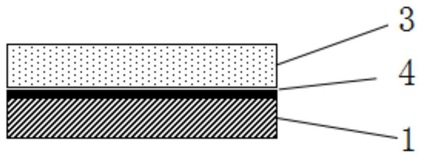
[0044] Such as Figure 1-Figure 7 As shown, this embodiment proposes a method for manufacturing a hydrogen-oxygen fuel cell plate, and making the hydrogen-oxygen fuel cell plate in Example 1 includes the following steps:

[0045] Step 1. Make cathode plate and cathode plate:

[0046] Make the anode plate: Prepare the gas-barrier conductive film 4, attach the first side of the gas-barrier conductive film 4 to the plane side of one of the hydrogen flow field plate 1 or the water flow field plate 2; attach the hydrogen flow field plate 1 or the water flow field plate The other plane side of the field plate 2 is attached to the second side of the gas barrier conductive film 4;

[0047] Make the cathode plate: prepare the gas-barrier conductive film 4, attach the first side of the gas-barrier conductive film 4 to the plane side of one of the air-oxygen flow field plate 3 or the water flow field plate 2; place the air-oxygen flow field plate 3 or The other plane side of the water ...


PUM


Abstract

The invention relates to the technical field of cell pole plates, in particular to a hydrogen-oxygen fuel cell pole plate. A hydrogen flow field plate, an air-oxygen flow field plate and a water flow field plate are plate-shaped bodies made of graphite and resin mixtures, one side surface of each of the hydrogen flow field plate, the air-oxygen flow field plate and the water flow field plate is a plane, the other side surface is provided with a flow field, one side of the plane of the hydrogen flow field plate and one side of the plane of the water flow field plate are attached to the two sides of one gas insulation conducting film to form an anode plate, one side of the plane of the air oxygen flow field plate and one side of the plane of the water flow field plate are attached to the two sides of the other gas insulation conducting film to form a cathode plate, and the outer side surface of the water flow field plate in the cathode plate and the outer side surface of the water flow field plate in the anode plate are mutually connected. The hydrogen-oxygen fuel cell pole plate has the advantages of convenience in processing, light weight and easiness in treatment of the redundant extension part of the pole plate. The invention also provides a manufacturing method of the hydrogen-oxygen fuel cell pole plate.

Description

technical field [0001] The invention relates to the technical field of battery electrode plates, in particular to a hydrogen-oxygen fuel cell electrode plate. Background technique [0002] The conventional fuel cell plate adopts a machine-added plate or a molded plate mixed with artificial graphite and resin. The porous skeleton is made of graphite, and the resin fills the voids of the skeleton to form a complete plate. Usually, holes caused by defects in the production process will appear in the process of plate processing, resulting in plate leakage and resulting in the scrapping of the plate. [0003] The electrode plate disclosed in the existing patent (publication number CN 109546158 A) includes two metal flow field plates, and the two metal flow field plates are respectively an anode side metal flow field plate and a cathode side metal flow field plate; each The two sides of the metal flow field plate are respectively a first surface and a second surface, the first s...

Claims


Application Information

Patent Timeline
Patent Type & Authority Applications(China)
IPC IPC(8): H01M8/0213H01M8/0221H01M8/0226H01M8/0258H01M8/1004
CPCH01M8/0213H01M8/0221H01M8/0226H01M8/0258H01M8/1004Y02E60/50
Inventor 华周发刘震陈煦帆
Owner 魔方氢能源科技(江苏)有限公司
Learn More