Printable Embroidery Machine

a printing machine and embroidery technology, applied in embroidering machines, automatic machines, textiles and paper, etc., can solve the problems of increasing the manufacturing cost of embroidery machines and the like, the drive of the sewing needle during sewing oscillates the needle bar case, and the sewing position accuracy of the embroidery pattern formed on the workpiece cloth can be reduced, and the position accuracy of the embroidery pattern can be improved. , the effect of reducing the size and the manufacturing cost of the frame drive uni

Inactive Publication Date: 2007-09-06
BROTHER KOGYO KK
View PDF13 Cites 5 Cited by
  • Summary
  • Abstract
  • Description
  • Claims
  • Application Information

AI Technical Summary

Benefits of technology

[0013] In the above-described construction, the frame drive unit has the mounting part which is detachably attached to the sewing machine body. The ink-jet printer is detachably attached to the mounting part of the frame drive unit separated from the sewing machine body. The printer is capable of printing the workpiece cloth moved by the cloth holding frame. Accordingly, either sewing machine body or printer can be attached to the frame drive unit reliably and reliably, whereby the workpiece cloth can be both sewn and printed without the re-holding of the workpiece cloth on the cloth holding

Problems solved by technology

Accordingly, a relatively larger amount of offset (a longer distance between the sewing needle and the print head) results in problems including a large-sized frame drive unit, reduction in a position accuracy of a sewing position of an embroidery pattern formed on workpiece cloth and a print position of a print pattern, a large-sized whole embroidery machine with increase in the provision of a printer on the sewing machine body and a large-sized frame drive unit, an increase in the manufacturing cost of the embroidery machine and the like.
On the other hand, however, the drive of the sewin

Method used


Image

  • Printable Embroidery Machine
  • Printable Embroidery Machine
  • Printable Embroidery Machine

Examples


first embodiment

[0032] the present invention will be described with reference to FIGS. 1 to 7.

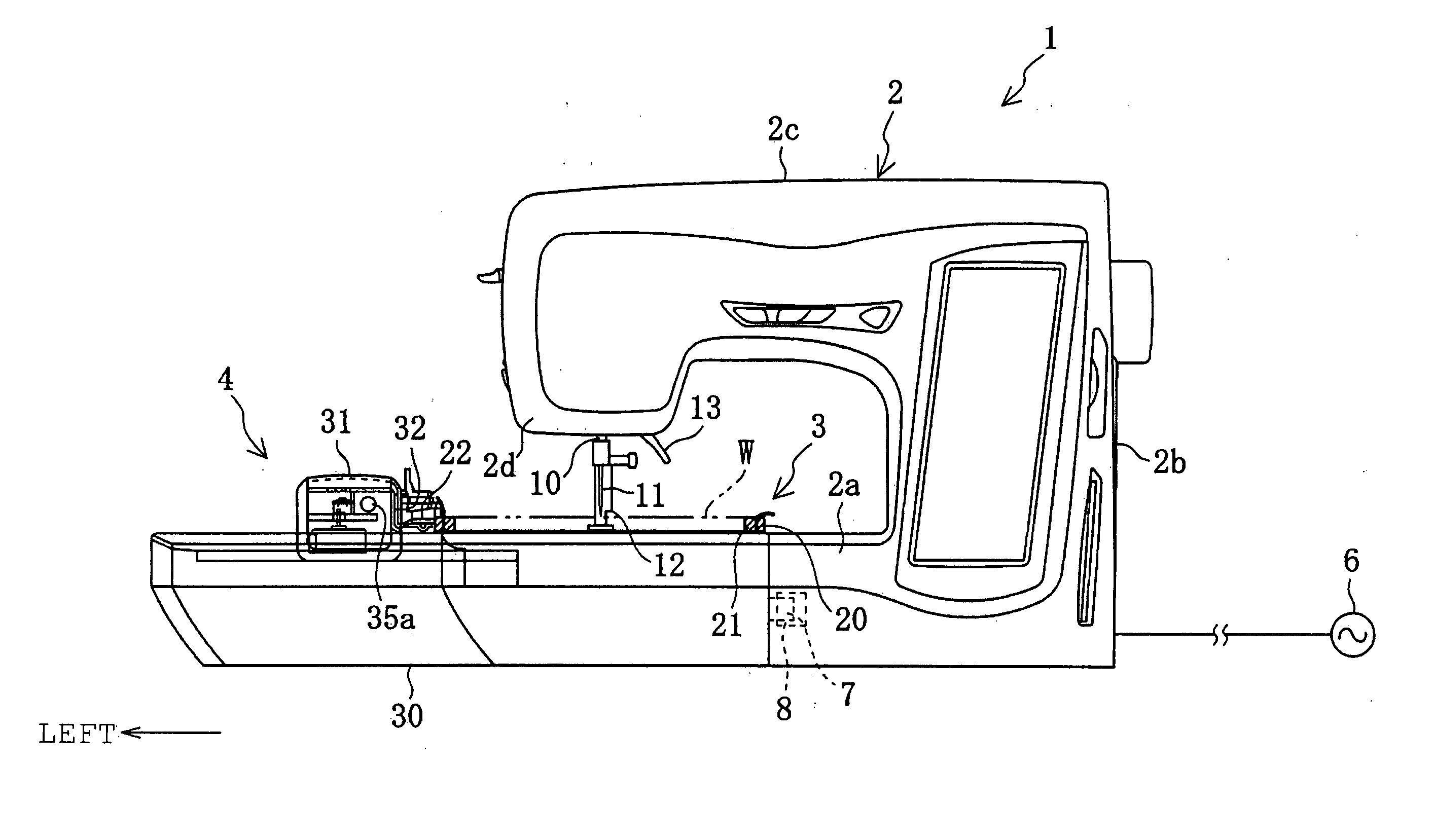
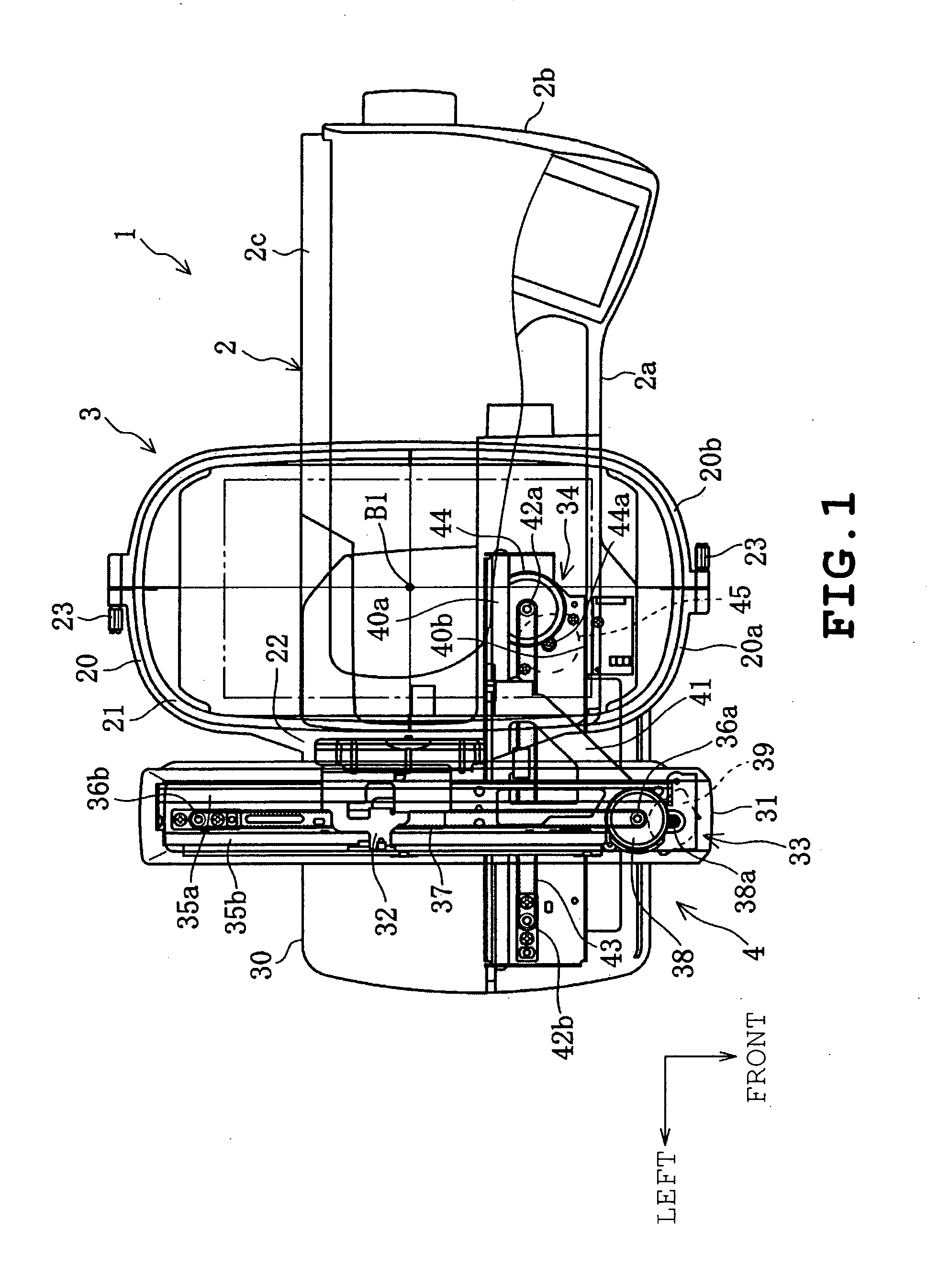
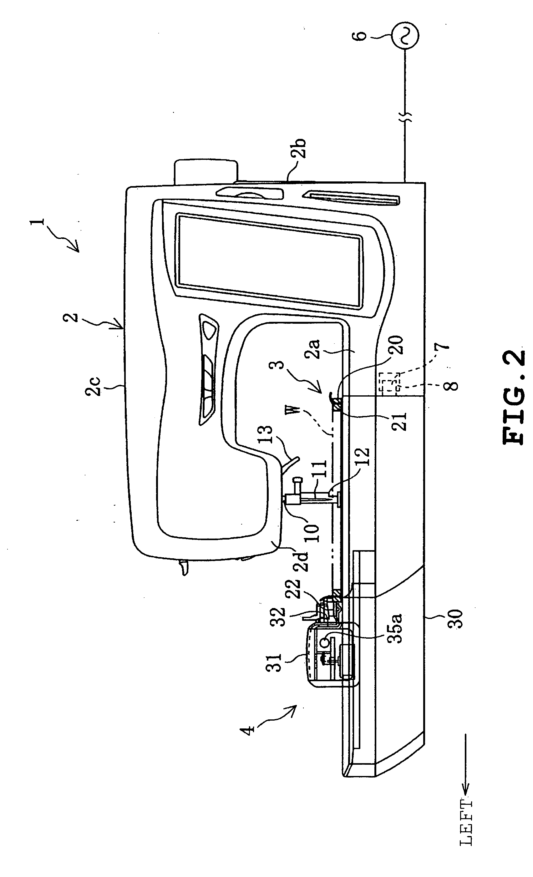
[0033] A printable embroidery machine 1 comprises a sewing machine body 2 capable of sewing workpiece cloth W, a cloth holding frame 3 holding the workpiece cloth W to be sewn and a frame drive unit 4 which has a mounting part 4a (see FIG. 3) detachably attached to the sewing machine body 2 and is coupled to the cloth holding frame 3 to move the cloth holding frame 3 independently both in cross and horizontal directions (in two horizontal directions perpendicular to each other), as shown in FIGS. 1 and 2.

[0034] An ink-jet printer 5 is detachably attached to the mounting part 4a of the frame drive unit 4 separated from the sewing machine body 2 so that the workpiece cloth W held on the cloth holding frame 3 moved by the frame drive unit 4 can be printed by the printer 5, as shown in FIGS. 3 to 8.

[0035] Firstly, the sewing machine body 2 will be described. The sewing machine body 2 has a bed 2a, a pillar 2...


PUM


Abstract

A printable embroidery machine (1), including a machine body (2) capable of sewing a workpiece cloth (W), a cloth holding frame (3) holding the workpiece cloth (W) to be sewn, and a frame drive unit (4) having a mounting part (4a) detachably attached to the machine body (2), and coupled to the cloth holding frame (3) to independently move the cloth holding frame in two horizontal directions perpendicular to each other. An ink-jet type printer (5) is detachably attached to the mounting part (4a) of the frame drive unit (4) separated from the machine body (2). The workpiece cloth (W) on the cloth holding frame (3) moved by the frame drive unit (4) can be printed by the printer (5).

Description

TECHNICAL FIELD [0001] This invention relates to a printable embroidery machine in which an ink-jet printer is attached to a frame drive unit separated from a machine body of the embroidery machine and which is constructed so as to be capable of printing workpiece cloth held on a cloth holder which is moved by the frame drive unit. BACKGROUND ART [0002] Embroidery machines conventionally comprise a machine body having a sewing needle capable of sewing workpiece cloth, a needle bar, a needle bar vertically driving mechanism and a thread take-up mechanism, a cloth holding frame holding workpiece cloth to be sewn in an extended state and a frame drive unit connected to and moving the cloth holding frame independently in two horizontal directions perpendicular to each other. The frame drive unit is attached to a bed of the machine body particularly in household embroidery machines and is detachable from the machine body in many household embroidery machines. [0003] Furthermore, an embro...

Claims


Application Information

Patent Timeline
IPC IPC(8): D05B21/00D05C3/00D05C3/02D05C7/04B41J2/01B41J2/165B41J2/18B41J3/407B41J3/42B41J3/44B41J29/00D05B19/02D05B39/00D05C7/02
CPCB41J2/16517B41J3/4078D05B39/00B41J2002/1742D05B19/02B41J3/445D06B11/0059
Inventor OGAWA, MASAOKITAZAWA, HIROSHI
Owner BROTHER KOGYO KK
Why Eureka
Try Eureka