Multimodular multistage high impact collision energy absorber

Inactive Publication Date: 2007-09-06
VINAYAGAMURTHY SRIDHARAN +1
View PDF6 Cites 7 Cited by
  • Summary
  • Abstract
  • Description
  • Claims
  • Application Information

AI Technical Summary

Benefits of technology

[0018] On a collision, the buffer plates behind the bumper of the host vehicle moves back into the cylindrical housing according to the velocity and momentum of the collision. The inner buffer plate then transfers the impact loads on to the outer convexity of the first of the sectional shear plate. This action in turn directs the force to be concentrated on the outer edges of the sectional shear plate on the shear groove. This shear groove facilitates shearing of the plates along the groove leaving the outer edge to remain in the inner groove of the cylindrical housing.
[0019] This process dissipates considerable energy as the shear happens only in response to an impact load of a high order. The sheared and dislocated first plate now impacts the second of the sectional plate being pushed on its re

Problems solved by technology

The suddenness with which collisions and impacts occur leaves little room for any active defense mechanisms to come into action in a meaningful way.
Designing crumple zones to absorb energy work to some extent, but in the process of energy absorption there is a very extensive damage to the vehicle even from minor impacts and a relatively large area is crumpled.
These actuators, sensors and other associated devices cost more and needs constant maintenance to keep them in working condition.
These systems are characterized by the high cost of manufacture and maintenance.
They also occupy considerable space and weigh heavily.
The disadvantage of these systems is that the dissipation characteristic remains the same, irrespective of the object with which collision occurs or the quantum of energy that is required to be dissipated.
The prior art of crumple zones, extra fenders, and a number of other modes and means of high energy impact absorption are plagued by inadequate, inconsistent and uneven deflection and absorption of impact resultant kinetic energy of very order and the protection afforded to th

Method used


Image

  • Multimodular multistage high impact collision energy absorber
  • Multimodular multistage high impact collision energy absorber
  • Multimodular multistage high impact collision energy absorber

Examples


Example

DETAILED DESCRIPTION OF THE INVENTION WITH REFERENCE TO DRAWINGS AND PREFERRED EMBODIMENT

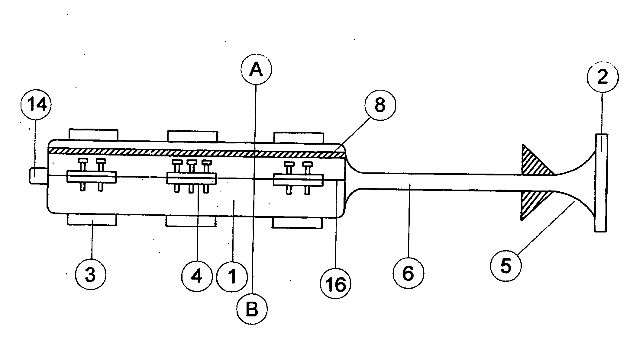
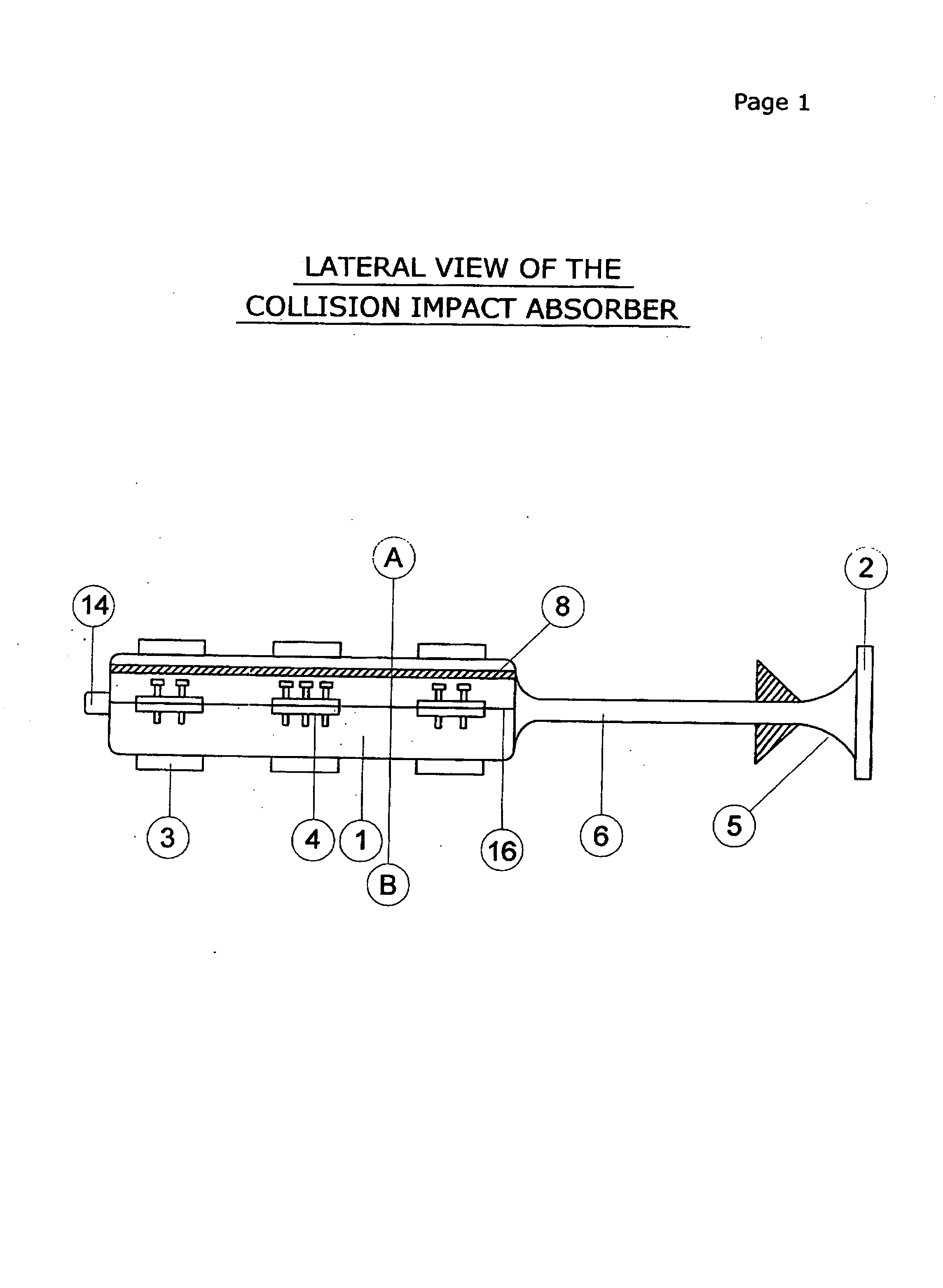
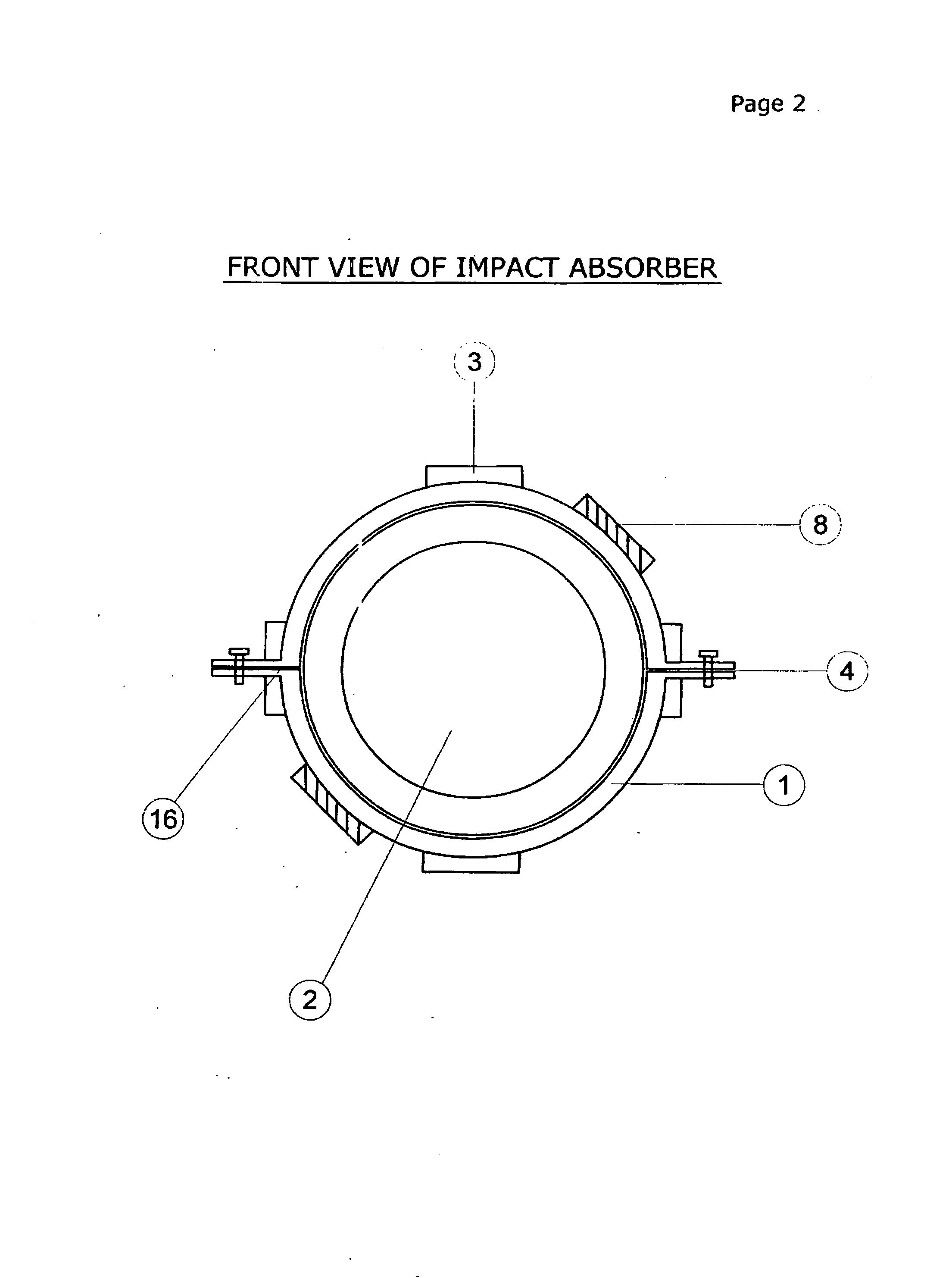
[0035] A preferred embodiment of the present invention, as well as objects, aspects, features and advantages, will be apparent and better understood from the following description in greater detail, of the illustrative and preferred embodiments thereof, which is to be read with reference to the accompanying drawings.

[0036] The accompanying drawings form a part of the specification, in which like numerals are employed to designate like parts of the same.

The Device

The Main Cylindrical Metallic Housing

[0037] The device consists of a hollow cylindrical metallic tube 1 made of high tensile steel of adequate wall thickness. The front and back of the cylinder is fitted with a flange plate integrated with the cylinder 1. The flange plates at the front and rear have a hole to accommodate the ram shaft. The cylinder is made up of two equal and symmetrical sections with seams 16 along the axis that a...


PUM


Abstract

This invention relates to a collision impact energy absorber that offers to absorb shock, impact and subsequent damage to vehicles in motion and other moving objects that require safety from impacts. This device fitted at appropriate impact zones of vehicles and crafts that move on and over land, air and water is capable of absorbing impacts of very high order and enhances the safety of lives and property. These can act in single units or in clusters where impacts of very high order are anticipated. The impact energy is directed into the hollow housing unit by a ram shaft that dislocates a series of vertically positioned sectional plates placed at intervals thereby absorbing the energy of the impacts on the host vehicle. This device is fitted as multimodular mode in tandem and also as multiple integrated modules to enhance its load dissipation efficiency.

Description

FIELD OF INVENTION [0001] The present invention relates to a safety device in the form of an impact energy absorber resulting from collisions. The collisions and their impact on the host vehicles that move on land, sea and air result in deformation and damage to a very high degree resulting in loss of life, injury and loss of property. Automobiles on road and helicopters are prone to collision and crashes. The impact faces of these vehicles absorb the energy by undergoing deforming in relation to the magnitude of the impact and the accompanying momentum. [0002] This device fitted alone, in pairs, clusters, in tandem units and in multiple series mode according to anticipated contingencies absorb the impact loads to a very large extent and thereby accords protection to life and property thereby reducing the likelihood of damage to the vehicle and its occupants. [0003] Essentially, the following are the matters that will be considered in relation to this invention. They are firstly the...

Claims


Application Information

Patent Timeline
IPC IPC(8): F16F7/12B60R19/26
CPCF16F7/125B60R19/34
Inventor VINAYAGAMURTHY, SRIDHARANVAIRAVAN, RAM
Owner VINAYAGAMURTHY SRIDHARAN
Why Eureka
Try Eureka